


15
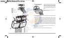
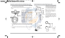
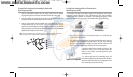
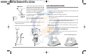
To mount the transducer pivot assembly to the bracket
(Dual frequency units):
1. Slide the assembled transducer into the metal bracket from the bottom,
aligning the large hole at the top of the bracket with the hole in the pivot.
2. Insert the headed pin through the pivot holes in the bracket and pivot. The
headed pin can be inserted from either side of the bracket.
3. Place the nylon washer over the opposite end of the headed pin. Place the
stainless washer over the 1/4"-20 x 5/8" screw threads, then insert into the
opposite end of the headed pin and finger tighten only. The screw has a thread
locking compound on the threads to prevent loosening, and should not be fully
tightened until all adjustments are made.
NOTE: The running position of the transducer is now completely adjustable. Subsequent
adjustment may be necessary to tweak the installation after high speed testing.
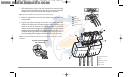
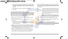
To adjust the running position of the transducer
(Dual frequency units):
The transducer mounting bracket allows height and tilt adjustment, while the pivot
bolt allows angular adjustment. These adjustments will help reduce cavitation.
Initially, adjust the transducer as described in the following paragraphs. Further
adjustment may be necessary to refine the installation after high-speed testing.
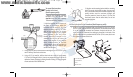
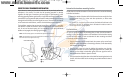
1. First, adjust the pivot angle of the transducer body, so it is parallel with the
length of the hull of the boat.
2. Fully tighten the two pivot screws, using the supplied Allen wrench. Access to
the pivot screws is provided by the lower holes in the side of the mounting
bracket. It may be necessary to re-tighten the pivot bolt after initial use as the
plastic may still be conforming to the pressure from the lock washers.
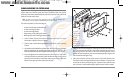
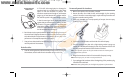
3. Adjust the height of the assembly so the face of the
transducer is 1/8" (3 mm) to 1/4" (6 mm) beneath the
bottom of the transom, and fully tighten the three
mounting screws.
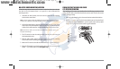
4. In order to gain access to the mounting screws, the
transducer assembly must be pivoted up in the bracket as
shown. Be careful not to alter the running angle as some
force is necessary to pivot the assembly.
Tighten the Mounting Screws
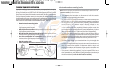
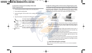
Cavitation that will cause
erratic sonar readings
Normal Cavitation
Screw
1
Headed Pin
2
Allen Wrench
3
Nylon Washer
4
Stainless Washer
5
3
1
5
4
2
93x_Man_531370-1_A - vs4.qxd 2/18/2005 11:11 AM Page 20