


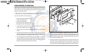
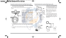
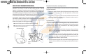

5. If access to the top mounting hole is not possible due to the selected height of
the transducer, fully tighten the two lower screws, then simply remove the
headed pivot pin and the transducer assembly, and tighten the top screw, then
reassemble.
6. Confirm that the pivot angle has not changed and that all mounting screws are
fully tightened.
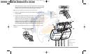
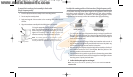
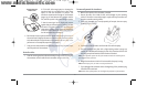
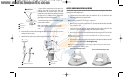
To route the transom transducer cable (all transducers):
The transducer cable has a low profile connector that must be routed to the point
where the control head is mounted. There are several ways to route the transducer
cable to the area where the control head will be installed. The most common
procedure routes the cable through the transom into the boat.
NOTE: Your transducer may not look exactly like the transducer shown in the illustrations,
but it will mount in exactly the same way.
NOTE: Your boat may have a pre-existing wiring channel or conduit that you can use for the
transducer cable.
1. Unplug the other end of the transducer cable from the control head. Make sure
that the cable is long enough to accommodate the planned route by running
the cable over the transom.
CAUTION! Do not cut or shorten the transducer cable, and try not to damage the cable insulation.
Route the cable as far as possible from any VHF radio antenna cables or tachometer cables to
reduce the possibility of interference. If the cable is too short, extension cables are available to
extend the transducer cable up to a total of 50' (15 m). For assistance, contact the Customer
Resource Center at www.humminbird.com or call 1-800-633-1468 for more information.
NOTE: Since the transducer may need to pivot up to 90° in the bracket if it strikes an object, make
sure there is sufficient cable slack to accommodate this motion. It is best to route the cable to the
side of the transducer so the cable will not be damaged by the rotation of the transducer.
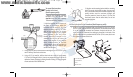
2. If you will be routing the cable through a hole in the transom, drill a 5/8"
diameter (16 mm) hole above the waterline. Route the cable through this hole,
then fill the hole with marine-grade silicone sealant and proceed to the next
step immediately.
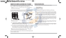
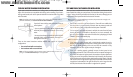
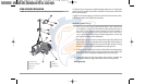
3. Place the escutcheon plate over the cable hole and use it as
a guide to mark the two escutcheon plate mounting holes.
Remove the plate, drill two 9/64" (3.5 mm) holes, then fill both
holes with marine-grade silicone sealant. Place the
escutcheon plate over the cable hole and attach with two
#8 x 5/8" (16 mm) wood screws.
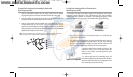
4. Route and secure the cable by attaching the cable clamp to
the transom; drill one 9/64" dia. (3.5 mm) x 5/8" deep (16 mm)
hole, then fill hole with marine-grade silicone sealant, then
attach the cable clamp using a #8 x 5/8" (16 mm) screw.
5. Plug the other end of the transducer cable back into the
control head connection holder.
To perform a final test of the transom transducer installation:
After transom transducer installation, please perform the final testing and then
finalize the installation (see Test and Finish the Transducer Installation).
16
93x_Man_531370-1_A - vs4.qxd 2/18/2005 11:11 AM Page 21