


19
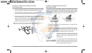
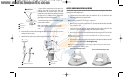
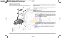
TROLLING MOTOR TRANSDUCER INSTALLATION
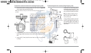
If you want to install the transducer on a trolling motor, use this procedure. Several
styles of the transducer are compatible with trolling motor mounting. If you have a
trolling motor bracket, refer to the separate installation instructions that are included
with the bracket.
NOTE: After trolling motor transducer installation, please perform the final testing and then
finalize the installation (see Test and Finish the Transducer Installation).
If you don’t have a trolling motor transducer, there are
several options:
• You may purchase a Trolling Motor Adapter kit that
will allow you to mount the transducer on the trolling
motor.
• You may also exchange your NEW and UNASSEMBLED
transducer (with mounting hardware included) for a
trolling motor transducer.
There are also several transducer switches available that support the following
configurations:
• Two control heads with one transducer
• Two transducers with one control head.
NOTE: Call the Humminbird® Customer Resource Center (1-800-633-1468) for details and
pricing, or visit www.humminbird.com for more information.
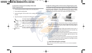
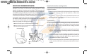
TEST AND FINISH THE TRANSDUCER INSTALLATION
When you have installed both the control head, the transducer, and accessories and
have routed all the cables, you must perform a final test before locking the transducer
in place. Testing should be performed with the boat in the water, although you can
initially confirm basic operation with the boat out of the water.
NOTE: If you have installed an in-hull mount transducer, this procedure does not apply, as the
transducer is already locked in place.
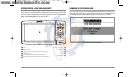
1. Press POWER once to turn the control head on. There will be an audible chirp
when the button is pressed correctly. If the unit does not power-up, make sure
that the connector holder is fully seated and that power is available.
2. If all connections are correct and power is available, the control head will enter
Normal operation. If no transducer is detected (or one is not connected), the
unit will go into Simulator mode and will indicate this by displaying the word
Simulator on the control head display.
NOTE: The transducer must be submerged in water for reliable transducer detection.
3. If the bottom is visible on-screen with a digital depth readout, the unit is
working properly. Make sure that the boat is in water greater than 2 ft (.6 m) but
less than the depth capability of the unit, and that the transducer is fully
submerged, since the sonar signal cannot pass through air.
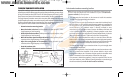
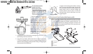
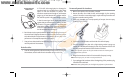
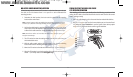
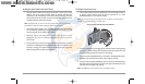
4. If the unit is working properly, gradually increase the boat speed to test
high-speed performance. If the unit functions well at low speeds but begins to
skip or miss the bottom at higher speeds, the transducer requires adjustment.
Angling the rear of the transducer downward and/or lowering the transducer
farther into the water will help achieve depth readings at high speeds. If the left
side of the fish arch is longer than the right side, then the back of the transducer
is angled too far downward. If the right side of the fish arch is longer than the
left side, then the back of the transducer is angled too far upwards.
93x_Man_531370-1_A - vs4.qxd 2/18/2005 11:11 AM Page 24