


4 - 3
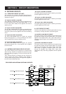
(1) AM DETECTOR CIRCUIT
The filtered signals are applied to the AM detector circuit
(Q201, Q202) to demodulate the 2nd IF signal into the AM AF
signals.
(2) FM AND WFM DETECTOR CIRCUIT
The filtered signals are applied to the limiter amplifier section
in the FM IF IC (IC151, pin 5), and then applied to the quad-
rature detector section to demodulate the 2nd IF signal into
FM and WFM AF signals.
The demodulated AM, FM or WFM signals are applied to the
AF amplifier circuit.
4-1-6 AF AMPLIFIER CIRCUIT (AF UNIT)
The AF amplifier circuit which is included a low-pass filter, AF
mute switch, AF volume controller and AF amplifier amplifies
the demodulated AF signals to drive a speaker.
(1) AM AND FM AF SIGNALS
The demodulated AM or FM (“DETO” signal) AF signals from
the AM detector (Q201, Q202) or FM detector (IC151, pin 9)
circuits are passed through the low-pass filter (Q204) via the
mode swtich (D201). The filtered signals are applied to the
1st AF amplifier (Q205).
(2) WFM AF SIGNALS
The demodulated WFM (“DETO” signal) AF signals from FM
detector (IC151, pin 9) circuit are bypassed the low-pass fil-
ter (Q204) via the mode swtich (D201). The demodulated
signals are applied to the 1st AF amplifier (Q205).
The amplified AF signals from the 1st AF amplifier (Q205) are
applied to the AF mute switch (Q251) which is controlled by
“MUTE” signal from the CPU (LOGIC unit; IC1, pin 48), and
are then applied to the electronic volume control circuit
(IC251, pin 6). The level controlled AF signals are output
from the volume IC (LOGIC unit; IC251, pin 7) and are then
applied to the AF power amplifier (IC252, pin 4). The power
amplified AF signals are then applied to the internal speaker
(LOGIC unit; SP1) through the “INTSP” signal via the [EXT
SP] jack (J253) when no plug is connected to the jack.
The AF filter circuit (LOGIC unit; IC241, pin 5) removes AF
signals below 300 Hz (CTCSS signals) for clear AF output
and these are applied to the CPU (LOGIC unit; IC1, pin 7) for
the CTCSS squelch detection via the “CTCIN” line.
The electronic volume control circuit controls AF gain, there-
fore, the AF output level is according to the [VOL] setting and
also the squelch conditions.
4-1-7 SQUELCH CIRCUIT(AF AND LOGIC UNITS)
• NOISE SQUELCH
The noise squelch circuit cuts out AF signals when no RF sig-
nals are received. By detecting noise components in the AF
signals, the squelch circuit switches the AF mute switch.
A portion of the AF signals from the FM IF IC (IC151, pin 9)
are applied to the active filter section (IC151, pins 7, 8). The
active filter section amplifies and filters noise components.
The filtered signals are applied to the noise detector section
and output from IC151 (pin 13) as the “NOISE” signal.
The “NOISE” signal from IC151 (pin 13) is applied to the CPU
(LOGIC unit; IC1, pin 47). The CPU analyzes the noise con-
dition and outputs the “MUTE” signal to AF mute switch
(Q251).
Even when the squelch is closed, the AF mute switch (Q251)
opens at the moment of emitting beep tones.
• TONE SQUELCH
The tone squelch circuit detects AF signals and opens the
squelch only when receiving a signal containing a matching
subaudible tone (CTCSS). When tone squelch is in use, and
a signal with a mismatched or no subaudible tone is
received, the tone squelch circuit mutes the AF signals even
when noise squelch is open.
A portion of the AF signals from the FM IF IC (IC151, pin 9)
passes through the low-pass filter (LOGIC unit; IC241, pins
5, 7) to remove AF (voice) signals and is applied to the
CTCSS decoder inside the CPU (LOGIC unit; IC1, pin 8) via
the “CTCIN” line to control the AF mute switch.
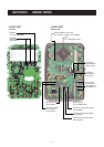
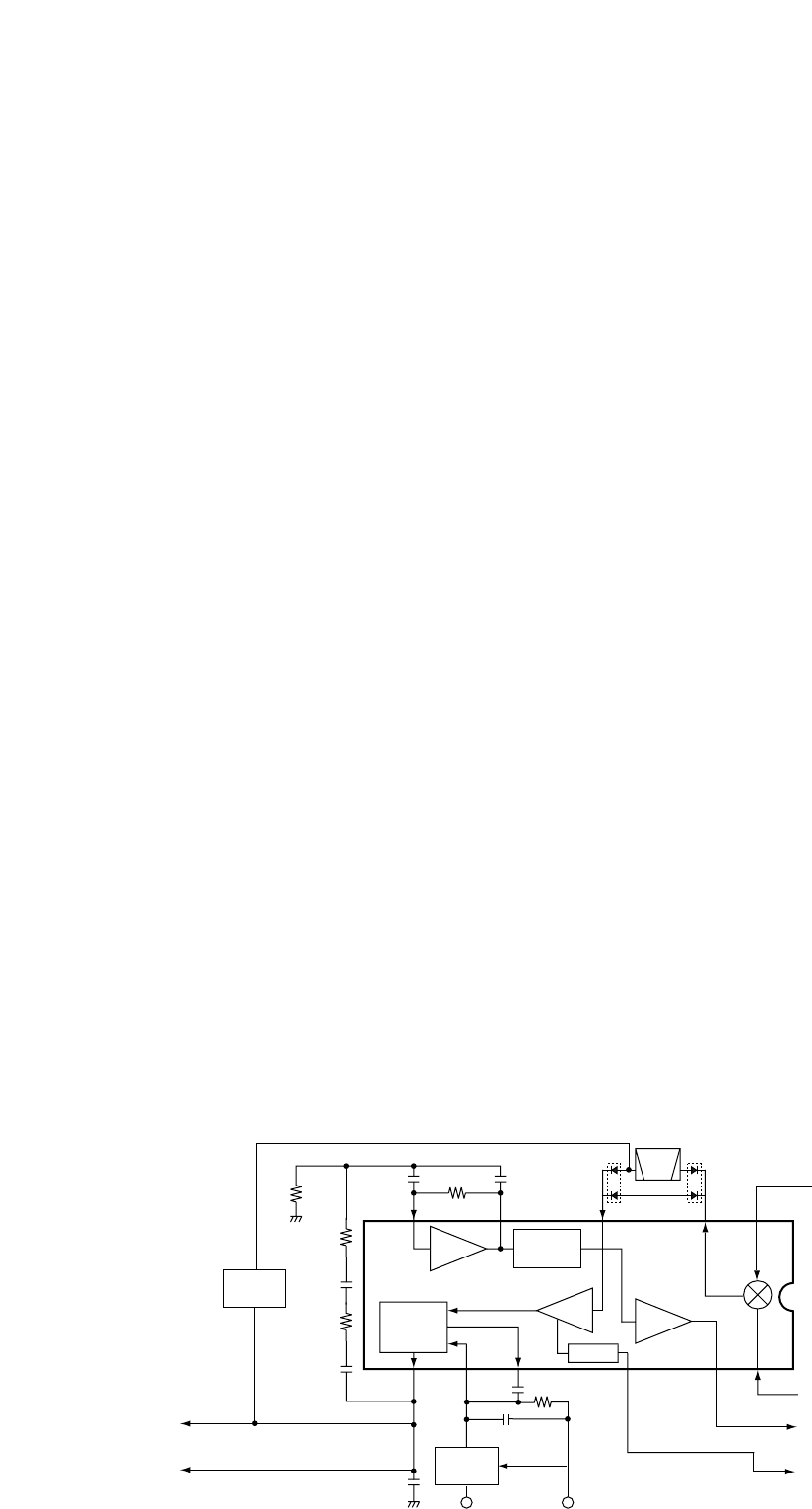
Mixer
16
Limiter
amp.
2nd IF filter
450 kHz
RSSI
IC151 TA31136FN
13
1st IF (69.45 MHz)
from IC351, pin 6 (RF unit)
"SD" signal to the CPU
pin 3
11
10
9
875 3
2
Active
filter
FI151
Noise
detector
FM
detector
Noise
comp.
"NOISE" signal to the CPU
pin 48
12
C154
C160
C161
C158
R167
R159
Q201,
Q202
R158
"DETO" signal to the low-pass
filter (LOGIC unit; IC241)
AF signal to the mode switch
(AF unit; Q203, D201)
2nd
Q207
R3VWFM
"2nd LO" signal from
X1 (RF unit)
C156
R155
R151
C155
AM
detector
WFM
CTRL
• 2ND IF AND DEMODULATOR CIRCUIT