


SECTION 4 CIRCUIT DESCRIPTION
4 - 1
4-1 RECEIVER CIRCUITS
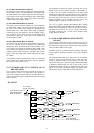
4-1-1 TRIPLEXER CIRCUIT (RF UNIT)
The transceiver has a triplexer (low-pass and bandpass fil-
ters) on the first stage from the antenna switching diode to
separate the signals.
• RF signals 0.495 MHz–75.995 MHz
The 0.495 MHz–75.995 MHz RF signals are passed through
the low-pass filters (L5, L6, L24, C43, C483–C486, L11–L13,
L17–L19, C21, C481, C482) and are applied to the antenna
switching circuit.
• RF signals 76.0 MHz–299.995 MHz
The 76.0 MHz–299.995 MHz RF signals are passed through
the low-pass (L5, L6, L24, C43, C483–C486) and high-pass
(L9, C9–C11) filters and are applied to the antenna switching
circuit.
• RF signals 230.0 MHz–629.995 MHz
The 230.0 MHz–629.995 MHz RF signals are passed
through the high-pass (L1, C1–C3) and low-pass (FI1) filters
and are applied to the antenna switching circuit.
• RF signals 630.0 MHz–999.990 MHz
The 630.0 MHz–999.990 MHz RF signals are passed
through the high-pass (L3, L4, C6–C8) filter and are applied
to the RF circuit.
4-1-2 ANTENNA SWITCHING CIRCUIT (RF UNIT)
The antenna switching circuit functions as a low-pass filter
while receiving. However, its impedance becomes very high
while transmitting by applying a current to D4, D6, D9, D12,
D13, D19.
Thus, tramsmit signals are blocked from the entering the
receiver circuits. The antenna switching circuit employs a
1/4λ type diode switching system. The signals are applied to
the each antenna switching circuit.
• RF signals 0.495 MHz–75.995 MHz
The signals pass through the antenna switching circuit (D9),
and then applied to the RF circuit.
• RF signals 76.0 MHz–299.995 MHz
The signals pass through the antenna switching circuit (D8),
and then applied to the RF circuit.
• RF signals 230.0.0 MHz–629.995 MHz
The signals pass through the antenna switching circuit (D7),
and then applied to the RF circuit.
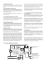
4-1-3 RF CIRCUIT (RF UNIT)
The RF circuit amplifies the received signals within the range
of frequency coverage and filters out-of-band signals.
(1) 0.495 MHz–29.995 MHz RF CIRCUIT
The signals from the antenna switching circuit pass through
the attenuator (D305) and band switch (D301). The signals
applied to the bandpass filter (L301, L302, C301–C307) to
suppress unwanted signals, then amplified at the RF amplifi-
er (Q302).
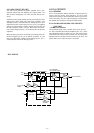
(2) 30.0 MHz–75.995 MHz RF CIRCUIT
The signals from the antenna switching circuit pass through
the attenuator (D305) and band switch (D306). The signals
applied to the bandpass filter (D307, D308, L303, L304,
C317–C320) to suppress unwanted signals, then pass
through the bandpass filter (D309, D310, L306, L307,
L323–C325, C331) after being amplified at the RF amplifier
(Q303).
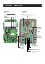
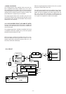
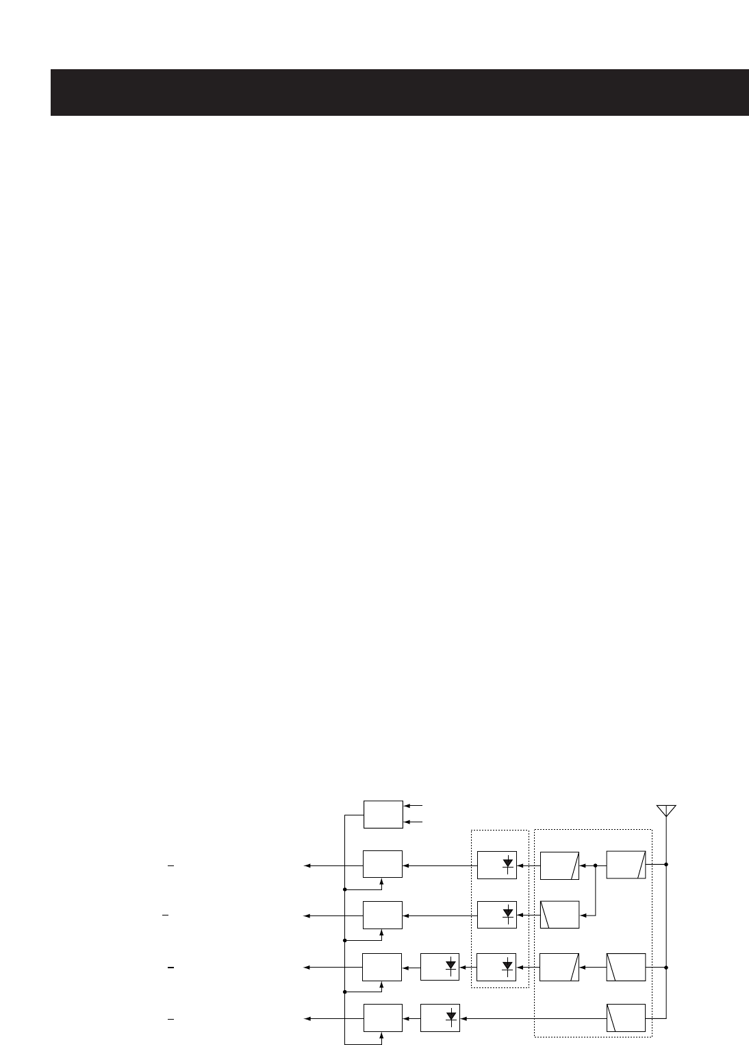
ANT
LPF
LPF
ATT
CTRL
HPF
HPF
HPF
LIMIT
LIMIT
ANT
SW
LPF
ANT
SW
ANT
SW
LIMIT
LIMIT
SW
SW
75.995 MHz RF signals
299.995 MHz RF signals
629.995 MHz RF signals
999.990 MHz RF signals
0.495 MHz
76.0 MHz
230.0 MHz
630.0 MHz
R3V
Q355
Antenna
switching
circuit
Triplexer
circuit
D305
D351
D401
D451
D6, D9
D4, D19
D12, D13
D457
D10
ATT
• TRIPLEXER AND ANTENNA SWITCHING CIRCUITS