


5 - 5
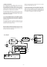
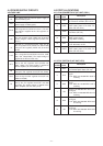
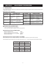
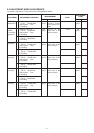
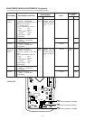
5-3 ADJUSTMENT MODE ADJUSTMENTS
The following adjustment must be performed at “ADJUSTMENT MODE”.
REFERENCE
FREQUENCY
OUTPUT
POWER
(11V 50 MHz
High power)
(11V 145 MHz
High power)
(11V 440 MHz
High power)
(11V 50 MHz
Low power)
(11V 145 MHz
Low power)
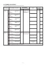
ADJUSTMENT
ADJUSTMENT ADJUSTMENT CONDITION
MEASUREMENT
VALUE
POINT
UNIT LOCATION UNIT ADJUST
1
1
2
3
4
5
6
7
8
9
10
• Displayed frequency :
(Fr ch.) 445.000 MHz
• Output power : Low
• Transmitting
• Displayed frequency :
(PH ch.) 50.000 MHz
• Output power : High
• Transmitting
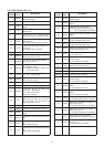
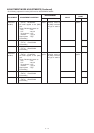
• Displayed frequency :
(PH ch.) 53.900 MHz
• Transmitting
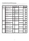
• Displayed frequency :
(PH ch.) 144.000 MHz
• Output power : High
• Transmitting
• Displayed frequency :
(PH ch.) 148.000 MHz
• Transmitting
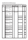
• Displayed frequency :
(PH ch.) 440.000 MHz
• Output power : High
• Transmitting
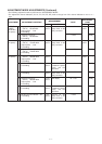
• Displayed frequency :
(PH ch.) 450.000 MHz
• Transmitting
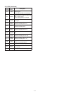
• Displayed frequency :
(PH ch.) 50.000 MHz
• Output power : Low
• Transmitting
• Displayed frequency :
(PH ch.) 53.900 MHz
• Transmitting
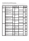
• Displayed frequency :
(PH ch.) 144.000 MHz
• Output power : Low
• Transmitting
• Displayed frequency :
(PH ch.) 148.000 MHz
• Transmitting
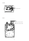
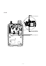
Top
panel
Top
panel
Top
panel
Top
panel
Top
panel
Top
panel
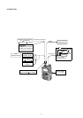
Loosely couple the
frequency counter
to the antenna con-
nector.
Connect an RF
power meter to the
[ANT] connector.
Connect an RF
power meter to the
[ANT] connector.
Connect an RF
power meter to the
[ANT] connector.
Connect an RF
power meter to the
[ANT] connector.
Connect an RF
power meter to the
[ANT] connector.
445.0000 MHz
5.0 W
5.0 W
5.0 W
5.0 W
5.0 W
5.0 W
0.5 W
0.5 W
0.5 W
0.5 W
Top
panel
Top
panel
Top
panel
Top
panel
Top
panel
Top
panel
[DIAL]
[DIAL]
[DIAL]
[DIAL]
[DIAL]
[DIAL]
[DIAL]
[DIAL]
[DIAL]
[DIAL]
[DIAL]