


5 - 7
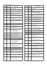
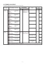
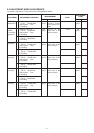
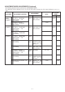
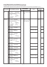
ADJUSTMENT MODE ADJUSTMENTS (Continued)
• The following adjustment must be performed at “ADJUSTMENT MODE”.
• The adjustment channel indicators (PL, DL, PH, DH, PE, DE) need to change from “DH” channel indicator to use “0” or “.”
keys.
OUTPUT
POWER
(8V 50 MHz
Low power)
(8V 145 MHz
Low power)
(8V 440 MHz
Low power)
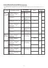
ADJUSTMENT
ADJUSTMENT ADJUSTMENT CONDITION
MEASUREMENT
VALUE
POINT
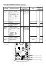
UNIT LOCATION UNIT ADJUST
7
8
9
10
11
12
13
14
15
16
• Displayed frequency :
(PH ch.) 50.000 MHz
• Output power : Low
• Transmitting
• Displayed frequency :
(PH ch.) 53.900 MHz
• Transmitting
• Displayed frequency :
(PH ch.) 144.000 MHz
• Output power : Low
• Transmitting
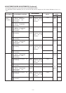
• Displayed frequency :
(PH ch.) 148.000 MHz
• Transmitting
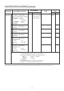
• Displayed frequency :
(DL ch.) 440.000 MHz
• Output power : Low
• Transmitting
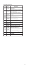
• Set the channel indicator : “PL”
• Transmitting
• Set the channel indicator : “DL”
• Transmitting
• Displayed frequency :
(DL ch.) 450.000 MHz
• Output power : Low
• Transmitting
• Set the channel indicator : “PL”
• Transmitting
• Set the channel indicator : “DL”
• Transmitting
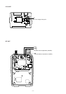
Top
panel
Top
panel
Front
panel
Side
panel
Top
panel
Front
panel
Side
panel
Top
panel
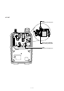
Connect an RF
power meter to the
[ANT] connector.
Connect an RF
power meter to the
[ANT] connector.
LCD display
Connect an amme-
ter between a power
supply and the
transceiver.
Connect an RF
power meter to the
[ANT] connector.
LCD display
Connect an amme-
ter between a power
supply and the
transceiver.
Connect an RF
power meter to the
[ANT] connector.
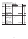
0.5 W
0.5 W
0.5 W
0.5 W
DL = “00”
1.1 A
0.5 W
DL = “00”
1.1 A
0.5 W
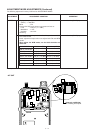
Top
panel
Top
panel
Top
panel
[DIAL]
[DIAL]
[DIAL]
[DIAL]
[DIAL]
[DIAL]
[DIAL]
[DIAL]
[DIAL]
[DIAL]