


5 - 1
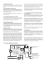
5-1 PREPARATION
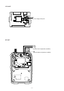
Some adjustments must be adjusted on the adjustment mode. When entering the adjustment mode, the 68 kΩ terminator (shown
at page 5-2) is required.
‘‘
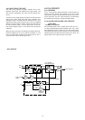
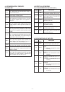
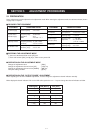
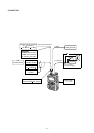
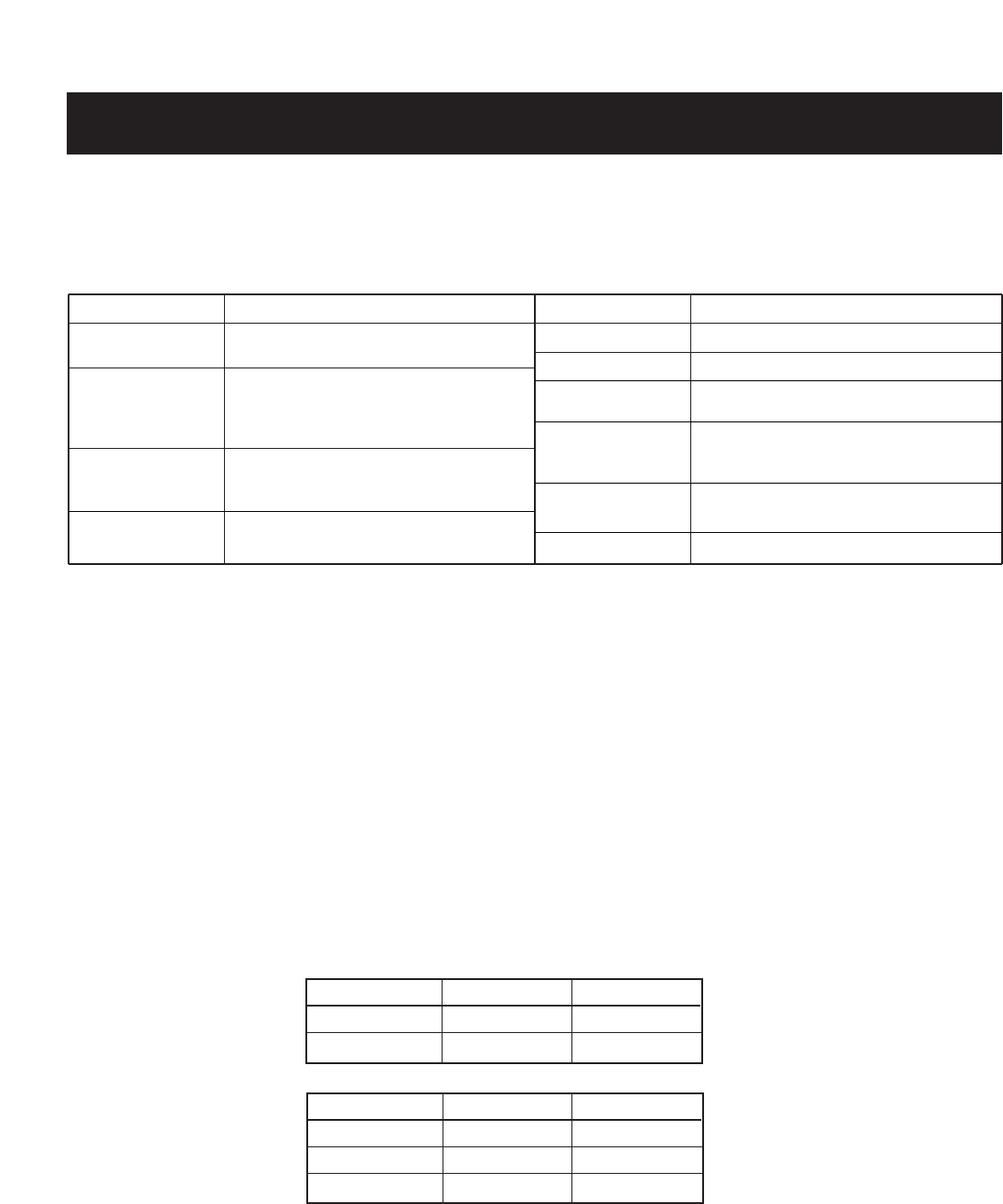
REQUIRED TEST EQUIPMENT
‘‘
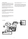
ENTERING THE ADJUSTMENT MODE
q Connect a 68 kΩ terminator to the [SP] jack.
w Push and hold the [SQL] and [8] keys, and then turn power ON.
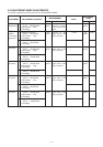
■ OPERATION ON THE ADJUSTMENT MODE
Change the adjustment value : [DIAL]
Change the adjustment channel or item [UP] : [VFO] key
Change the adjustment channel or item [DOWN] : [MR] key
Verify the setting condition : [8] key
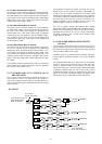
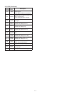
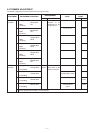
■ OPERATION ON THE “OUTPUT POWER” ADJUSTMENT
When adjusting the “OUTPUT POWER” adjustment, need to change the adjustment channel indicator manually.
When displayed channel indicator “DH” on the LCD at first, push the “0” or “.” keys to change the channel indicator as follow.
EQUIPMENT
DC power supply
RF power meter
(terminated type)
Frequency counter
FM deviation meter
GRADE AND RANGE
Output voltage : 11 V DC
Current capacity : 3 A or more
Measuring range : 1–10 W
Frequency range : 28–600 MHz
Impedance : 50 Ω
SWR : Less than 1.2 : 1
Frequency range : 0.1–600 MHz
Frequency accuracy: ±1 ppm or better
Sensitivity : 100 mV or better
Frequency range : 30–600 MHz
Measuring range : 0 to ±10 kHz
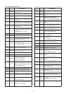
EQUIPMENT
Ammeter
DC voltmeter
Audio generator
Standard signal
generator (SSG)
Oscilloscope
Attenuator
GRADE AND RANGE
Measuring capacity : 10 A and 30 A
Input impedance : 50 kΩ/V DC or better
Frequency range : 300–3000 Hz
Measuring range : 1–500 mV
Frequency range : 1–1300 MHz
Output level : 0.1 µV–32 mV
(–127 to –17 dBm)
Frequency range : DC–20 MHz
Measuring range : 0.01–20 V
Power attenuation : 40 or 50 dB
SECTION 5 ADJUSTMENT PROCEDURES
Pushing key
“0” key
“0” key
LCD (Before)
DH
PH
LCD (After)
PH
DH
Pushing key
“.” key
“.” key
“.” key
LCD (Before)
DH
DL
DE
LCD (After)
DL
DE
DH