


4 - 6
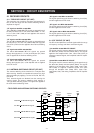
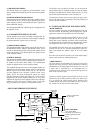
• 430 MHz VCO CIRCUIT
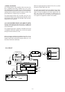
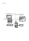
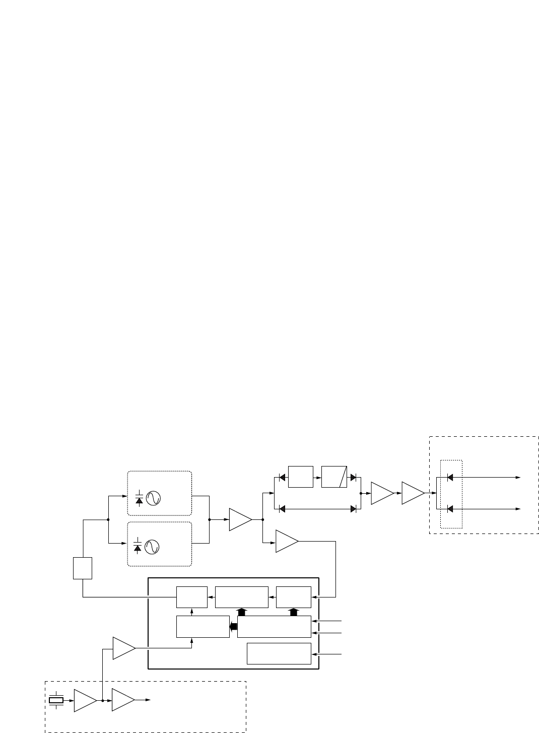
The oscillated signal at the 430 MHz VCO circuit (Q4, Q5,
D3) is amplified at two buffer amplifiers (Q7, Q11), and is
then applied to the PLL IC (IC201, pin 19). The signal is divid-
ed by serial data from the CPU (LOGIC unit; IC1) and phase-
detected with the divided reference frequency (5 kHz). The
phase difference is output from pin 5 as pulses.
The output signals from the PLL IC (IC201, pin 5) are con-
verted to DC voltages (lock voltage) by the loop filter, and are
then fed back to the 144 MHz and 430 MHz VCO circuits to
stabilize the VCO frequency.
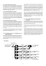
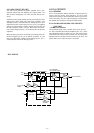
4-3-3 VCO DIVIDER CIRCUIT (VCO AND RF UNITS)
The PLL circuit employs the two VCO circuits (144 MHz and
430 MHz) and VCO divider (IC1) to transmit on 3 bands and
receive wide band.
The oscillated signal at the 144 MHz or 430 MHz VCO circuit
is amplified at the buffer amplifier (Q7), and is then passed
through the divider switch (D7, D8).
When the signal is applied to the divider circuit (IC1, pin 2),
the circuit divides the VCO signal into the ratio of 1/2. The
divided signal passes through the low-pass filter (L12, L13,
C48–C51) and divider switch (D9).
When the signal bypasses the divider circuit (IC1), it passes
through the divider switch (D8, D10).
The VCO signal is applied to the LO amplifiers (Q16, Q212),
and then passed through the transmit/receive switch (D21,
D202). The signal is applied to the buffer amplifier (RF unit;
IC51, pin 1) for the TX LO frequency, or applied to the 1st
mixer circuit (IC351, pin 3) for the RX 1st LO frequency as
“LO” signal via or bypass the doubler circuit (Q354).
Shift register
Prescaler
Phase
detector
Loop
filter
Programmable
counter
PLL lock detector
Programmable
divider
X1
13.8 MHz
Q1, Q2,
D1
430 MHz VCO
50, 144MHz VCO
Buff.
Q11
Q7
D7
D8
D9
D10
Q206,
Q207
3
4
PLSTB
IC201 (PLL IC)
AF UNIT
RF UNIT
CLK
7
UNLK
to transmitter circuit
to 1st mixer circuit
(IC351, pin 3)
15
13
19
Q3, Q4,
Q5,
D3, D4
1/2 LPF
Buff.
Q16
LO
Q212
TX/RX
switch
D51
D201
LO
Q2
to FM IF IC (IC151, pin 2)
Amp.
Q211
Amp.
Buff.
Q1
• PLL CIRCUIT