


5 - 11
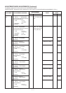
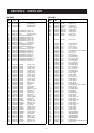
ADJUSTMENT MODE ADJUSTMENTS (Continued)
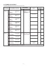
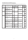
The following adjustment must be performed at “ADJUSTMENT MODE”.
“DETECTOR COIL” adjustment must be performed on same channel as “DTCS DEVIATION ADJUSTMENT” (DT ch.).
DETECTOR
COIL
RF
TRACKING
ADJUSTMENT
ADJUSTMENT ADJUSTMENT CONDITION
MEASUREMENT
VALUE
POINT
UNIT LOCATION UNIT ADJUST
1
1
2
3
4
5
6
7
8
9
10
• Displayed frequency :
(DS ch.) 445.000 MHz
• Connect the SSG to the antenna
connector and set as:
Level : 1.0 µV*
(–47 dBm)
Modulation : OFF
• Receiving
• Displayed frequency :
(TL ch.) 30.100 MHz
• Connect the SSG to the antenna
connector and set as:
Level : 0.5 µV
*
(–113 dBm)
Modulation : 1 kHz
Deviation : ±3.5 kHz
• Receiving
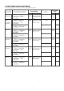
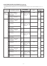
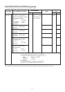
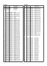
• Displayed frequency :
(TH ch.) 47.100 MHz
• Receiving
• Displayed frequency :
(TL ch.) 48.100 MHz
• Receiving
• Displayed frequency :
(TH ch.) 75.100 MHz
• Set the SSG as:
Level : 1 µV
*
(–107 dBm)
• Receiving
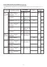
• Displayed frequency :
(TL ch.) 76.100 MHz
• Set the SSG as:
Level : 1 µV
*
(–107 dBm)
• Receiving
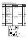
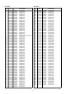
• Displayed frequency :
(TH ch.) 149.100 MHz
• Receiving
• Displayed frequency :
(TL ch.) 150.100 MHz
• Receiving
• Displayed frequency :
(TH ch.) 229.100 MHz
• Set the SSG as:
Level : 3.2 µV
*
(–97 dBm)
• Receiving
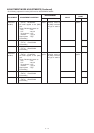
• Displayed frequency :
(TL ch.) 280.100 MHz
• Receiving
• Displayed frequency :
(TM ch.) 370.100 MHz
• Set the SSG as:
Level : 0.5 µV
*
(–113 dBm)
• Receiving
AF
AF
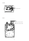
Connect a multime-
ter to check point
CP0.
Connect a DC volt-
meter or oscillo
scope to the IC151,
pin 12 (“SD” line).
1.0 V
Maximum voltage
Maximum voltage
Maximum voltage
Maximum voltage
Maximum voltage
Maximum voltage
Maximum voltage
Maximum voltage
Maximum voltage
Maximum voltage
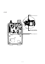
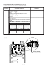
AF
Top
panel
L151
[DIAL]
[DIAL]
[DIAL]
[DIAL]
[DIAL]
[DIAL]
[DIAL]
[DIAL]
[DIAL]
[DIAL]
*This output level of the standard signal generator (SSG) is indicated as SSG’s open circuit.