


5 - 3
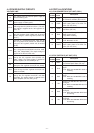
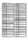
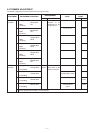
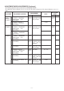
5-2 TRIMMER ADJUSTMENT
The following adjustment must be performed on the normal mode.
PLL LOCK
VOLTAGE
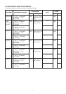
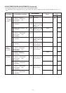
POWER
BALANCE
ADJUSTMENT
ADJUSTMENT ADJUSTMENT CONDITION
MEASUREMENT
VALUE
POINT
UNIT LOCATION UNIT ADJUST
1
2
3
4
5
6
1
2
3
4
5
• Displayed frequency
: 30.000 MHz
• Mode : FM
• Receiving
• Displayed frequency
: 29.995 MHz
• Mode : FM
• Receiving
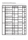
• Displayed frequency
: 150.000 MHz
• Mode : WFM
• Receiving
• Displayed frequency
: 169.995 MHz
• Mode : WFM
• Receiving
• Displayed frequency
: 550.000 MHz
• Mode : WFM
• Receiving
• Displayed frequency
: 629.990 MHz
• Mode : FM
• Receiving
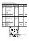
• Displayed frequency
: 144.000 MHz
• Transmitting
• Displayed frequency
: 148.000 MHz
• Transmitting
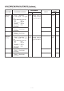
• Displayed frequency
: 440.000 MHz
• Transmitting
• Displayed frequency
: 460.000 MHz
• Transmitting
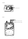
VCO
Top
panel
Connect the DC
voltmeter or an
oscilloscope to the
checkpoint “CP”.
Connect an RF
power meter to the
antenna connector.
0.4 V–1.0 V
7.0 V–11.0 V
0.7 V–2.0 V
7.0 V–11.0 V
0.6 V–1.2 V
7.0 V–11.0 V
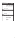
144.000 MHz’s power
Same value as
144.000 MHz’s power
440.000 MHz’s power
Same value as
440.000 MHz”s
power
RF
Verify
Verify
verify
Verify
Verify
Verify
L19
L19
L16,
L456
L16,
L456
• Same adjustments as steps 1–4 several times.