


3 - 1
SECTION 3 DISASSEMBLY INSTRUCTIONS
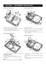
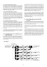
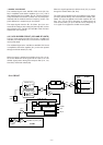
1. Removing the rear panel
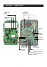
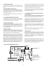
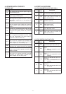
2. Removing the LOGIC unit
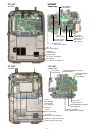
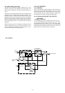
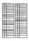
3. Removing the AF unit
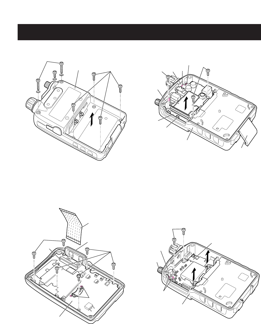
4. Removing the RF unit
q Unscrew 1 screw A (M2 × 4 mm, black).
w Unscrew 2 screws B (M2 × 20 mm, black), and 4 screws
C (M2 × 6 mm, black) from the rear panel.
e Take off the rear panel in the direction of the arrow.
q Unplug the flexible cable W1 from J1 on the LOGIC unit
to separate the rear panel.
w Take off the main seal.
e Unsolder 2 points D at the speaker lead.
r Unscrew 6 screws E (2 × 4 mm, silver) to separate the
LOGIC unit.
NOTE:
When you tighten 6 screws E, tighten those in turn of 1–6.
q Take off the lock plate.
w Unsolder 5 points F at the antenna plate, vol plate and
lead.
e Unscrew 1 screw G (2 × 4 mm, silver), and 2 screws H
(M2 × 12 mm, black) from the AF unit.
r Take off the AF unit in the direction of the arrow to sepa-
rate the rear panel.
q Unsolder 2 points I at the antenna rug plate and anten-
na connector.
w Unscrew 2 screws J (M2 × 4 mm, silver) from the FRONT
panel.
e Take off the RF unit in the direction of the arrow to sepa-
rate the rear panel.
Rear panel
A
B
C
W1 (L)
J1
Main seal
E
E
2
3
4
5
LOGIC unit
1
6
D
G
J251
Lock plate
Rear panel
AF unit
Vol plate
Vol lead
Antenna
plate
F
F
F
H
J
RF unit
Antenna rug
Antenna
connector
Rear panel
I