


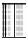
5 - 13
RF
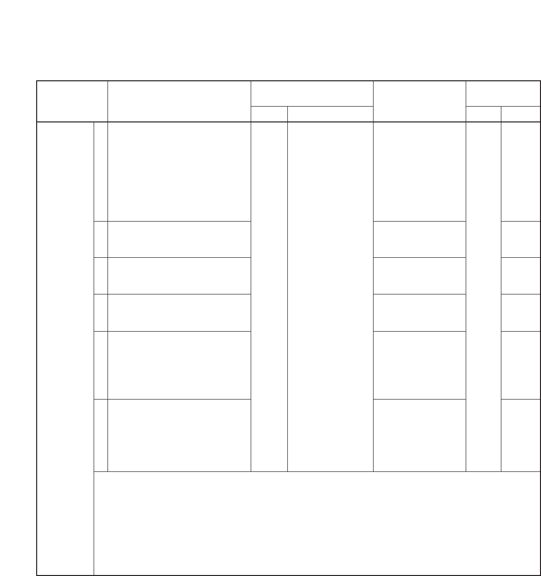
TRACKING
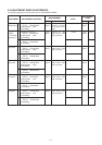
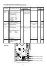
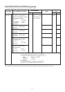
ADJUSTMENT MODE ADJUSTMENTS (Continued)
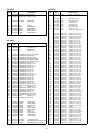
The following adjustment must be performed at “ADJUSTMENT MODE”.
ADJUSTMENT
ADJUSTMENT ADJUSTMENT CONDITION
MEASUREMENT
VALUE
POINT
UNIT LOCATION UNIT ADJUST
11
12
13
14
15
16
• Displayed frequency :
(TM ch.) 430.100 MHz
• Connect the SSG to the antenna
connector and set as:
Level : 0.5 µV*
(–113 dBm)
Modulation : 1 kHz
Deviation : ± 3.5 kHz
• Receiving
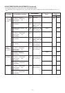
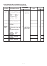
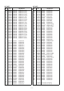
• Displayed frequency :
(TH ch.) 499.100 MHz
• Receiving
• Displayed frequency :
(TL ch.) 450.100 MHz
• Receiving
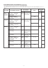
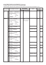
• Displayed frequency :
(TH ch.) 569.100 MHz
• Receiving
• Displayed frequency :
(TL ch.) 630.100 MHz
• Set the SSG as:
Level : 1 µV
*
(–107 dBm)
• Receiving
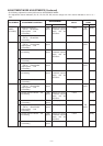
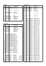
• Displayed frequency :
(TH ch.) 900.100 MHz
• Set the SSG as:
Level : 3.2 µV
*
(–97 dBm)
• Receiving
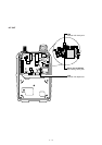
AF Connect a DC volt-
meter or oscillo
scope to the IC151,
pin 12 (“SD” line).
Maximum voltage
Maximum voltage
Maximum voltage
Maximum voltage
Maximum voltage
Maximum voltage
Top
panel
[DIAL]
[DIAL]
[DIAL]
[DIAL]
[DIAL]
[DIAL]
*This output level of the standard signal generator (SSG) is indicated as SSG’s open circuit.
When adjusting by automatically, must change the SSG’s level which is depened on adjustment frequencies as shown above.
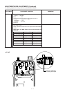
CONVENIENT: The “RF TRACKING” can be adjusted automatically.
q: Set the Displayed frequency (TL ch.) 30.100 MHz
w: Connect the SSG to the antenna connector and set as:
Level : 0.5 µV* (–113 dBm)
Modulation : 1 kHz
Deviation : ± 3.5 kHz
e: Receiving
r: Push the [BAND] key to start tuning, automatically.
t: Repeat q-r to perform additional frequencies.