


4 - 8
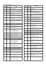
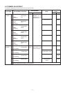
Pin Port
Description
number name
Pin Port
Description
number name
1
3
5
6
7
12
13
14
19
25
26
28
29
30
31
33
34
35
40
42
43
44
45
PATMP
SD
CHG
VIN
CTCIN
WFM
AM
CLSFT
RESET
POWER
CPUHV
IOSTB
DASTB
CLIN
CLOUT
PDAUL
CK
PLSTB
ECK
CHGC
PCON
R3C
TXC
Input port for the PA’s temperature
while transmitting.
Input port for the S-meter signal.
Input port for the battery voltage divide
signal.
Input port for the power supply voltage
divide signal.
Input port for the CTCSS decorded
signal (67.0–254.1 Hz analog signal).
Outputs the FM or WFM regulator
control signal.
Low: FM or WFM mode is selected.
Outputs the AM mode regulator con-
trol signal.
Low: AM mode is selected.
Outputs the clock shift control signal.
Input port for the CPU reset signal.
High: The CPU is reset.
Input port for the [POWER] switch.
Low: Power is ON.
Input port for the external power sup-
ply connecting signal.
Low: While the external power sup-
ply is connected.
Outputs the expander IC (AF unit;
IC51, pin 1) strobe signal.
Outputs strobe signals to the D/A IC
(RF unit; IC251, pin 2).
Input port for the cloning signal.
Output port for the cloning signal.
I/O port for the PLL IC (VCO unit;
IC201, pin 7) data signal.
Low: PLL is unlocked.
High: PLL is locked.
Outputs clock signals to the R3V
switch (AF unit; IC51, pin 3), D/A IC
(RF unit; IC251, pin 3) and PLL IC
(VCO unit; IC201, pin 4).
Outputs the PLL IC strobe signal.
Outputs the EEPROM clock signal.
Outputs the battery charger control
signal.
Outputs the +3C regulator control sig-
nal.
Outputs the R3C regulator control sig-
nal.
Low: While receiving.
Outputs the T5V regulator control sig-
nal.
High: While transmitting.
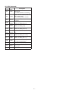
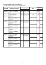
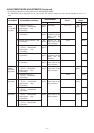
46
47
48
49
51
52
53
54
55
56
57
58–61
62–65
66–69
70
71
72
73
74
75
77
81
82
Outputs the mic amplifier regulator
control signal.
Input port for the SQL detection noise
signal.
Outputs mute control signal.
High: AF muting while receiving.
MIC muting while transmitting.
Output AF amplifier regulator control
signal.
Outputs BUSY LED control signal.
High: The BUSY LED is ON.
Outputs key backlight control signal.
High: Green backlight is ON.
Outputs key backlight control signal.
High: Red backlight is ON.
Outputs LCD backlight control signal.
Low: Lights ON.
Outputs the 430 MHz VCO regulator
control signal.
Low: 430 MHz is selected.
Input port for the up/down signal from
the main dial (AF unit; S251).
Output ports for key matrix.
Output ports for Initial matrix.
Input ports for key matrix.
Outputs the 50 MHz VCO regulator
control signal.
Low: 50 MHz is selected.
Input port for the volume level control
signal.
Low: Volume level is low.
Input port for the volume level control
signal.
Low: Volume level is high.
Input port for the [SQL] switch.
Low: While [SQL] switch is pushed.
Outputs the 430 MHz modulation cir-
cuit control signal.
Low: While 430 MHz is transmitting.
Outputs the 144 MHz modulation cir-
cuit control signal.
Low: While 144 MHz is transmitting.
Input port for the [PTT] switch.
High: While [PTT] switch is pushed.
Outputs 144 MHz VCO regulator con-
trol signal.
Low: 144 MHz is selected.
Outputs the VCO select signal.
MICC
NOISE
MUTE
AFON
BUSYL
GLED
RLED
LCDL
V3C
DIUD
DICK
KS3–KS0
I3–I0
KR3–KR1
V1C
VOLDN
VOLUP
SQL
430M
144M
PTT
V2C
VSFT
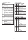
4-5-3 CPU (LOGIC UNIT; IC1)