


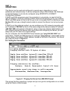
7
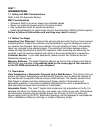
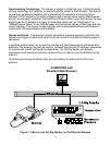
2.5 Network Communication Interfaces
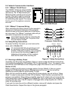
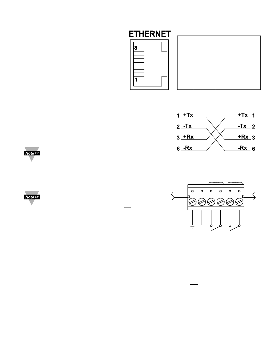
2.5.1 10Base-T RJ-45 Pinout
The 10BASE-T Ethernet network (RJ45)
system is used in the iServer for network
connectivity. The 10 Mbps twisted-pair
Ethernet system operates over two pairs
of wires. One pair is used for receiving
data signals and the other pair is used
for transmitting data signals. This means
that four pins of the eight-pin connector
are used.
2.5.2 10Base-T Crossover Wiring
When connecting the iServer directly to the computer’s
network port, the transmit data pins of the computer
should be wired to the receive data pins of the iServer,
and vice versa. The 10Base-T crossover cable with pin
connection assignments are shown below.
Use straight through cable for connecting the
iServer to an Ethernet hub. The ports on the
hub are already crossed.
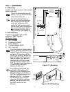
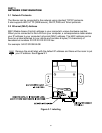
2.6 Relay Wiring Connections
To access the Relay Connector you must remove the
cover, refer to Section 2.4.
It is recommended that you ground your unit
by connecting a wire to the Ground/Return
position of the relay connector. Or
by wrapping
a wire around the mounting tab screw and
tightening a lock washer so that it embeds
itself into the metal of the mounting tab.
2.7 Running on Battery Power
The battery and S5 jumper are installed: if there is a power outage the iServer board will be
fully functional including the LCD backlight “ON” for approximately 1 hour. You need to make
sure that the LCD/PWR field on the Configuration page of the iServer is set to UPS (see
Section 4.3.5.F)
Battery installed and S5 jumper in storage position (Factory Default): if there is a power
outage the LCD Backlight and iServer Ethernet board will not run, but
the unit will be
collecting and storing data for approximately 10 days.
When you first connect the battery, without the AC power adaptor, the unit will be in “Sleep
Mode”, in order to save power, and the LCD will display “Flash Standby” (provided that S5
jumper is not installed). When battery is installed, plug the AC adaptor into unit and push the
Flash Reset Button (refer to Figure 2.3 or Figure 2.4). Unit is now ready to be configured for
recording the data. Also, if the AC adaptor is unplugged after configuring the unit, it will be
ready for recording data.
If you want to move the unit to a different location, remove AC adaptor and press the
Flash Reset button. Repeat the steps in the above paragraph.
623451
NO1
NO2
9 Vdc
RTN
COM2
COM1
RELAY 2 RELAY 1
Figure 2.7 Relay Connections
Figure 2.6 10Base-T
Crossover Cable Wiring
Pin Name Description
1 +Tx + Transmit Data
2 -Tx - Transmit Data
3 +RX + Receive Data
4 N/C Not Connected
5 N/C Not Connected
6 -Rx - Receive Data
7 N/C Not Connected
8 N/C Not Connected
Figure 2.5 RJ45 Pinout