


LIST OF FIGURES:
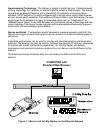
Figure 1.1 iServer and iLD Big Display on the Ethernet Network........................3
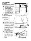
Figure 2.1 Mounting ................................................................................................4
Figure 2.2 DIP Switches...........................................................................................4
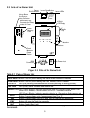
Figure 2.3 Parts of iServer Unit...............................................................................5
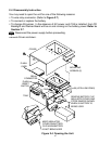
Figure 2.4 Opening the Unit ....................................................................................6
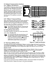
Figure 2.5 RJ45 Pinout ............................................................................................7
Figure 2.6 10Base-T Crossover Cable Wiring .......................................................7
Figure 2.7 Relay Connections ................................................................................7
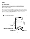
Figure 3.1 Labeling ..................................................................................................8
Figure 3.2 DIP Switch on Bottom Side of iServer..................................................9
Figure 3.3 Telnet Login into the iServer ...............................................................10
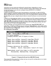
Figure 4.1 Pinging the iServer from MS-DOS Prompt ........................................11
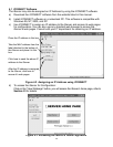
Figure 4.2 Assigning an IP Address using iCONNECT ......................................12
Figure 4.3 Accessing the iServer’s Home Page Menu........................................12
Figure 4.4 Access Control ...................................................................................13
Figure 4.5 iServer Home Page ..............................................................................14
Figure 4.6 Login and Administration Password .................................................14
Figure 4.7 Read Sensor .........................................................................................15
Figure 4.8 Adjustable Chart...................................................................................17
Figure 4.9 iFLASH Download Utility .....................................................................18
Figure 4.10 Access Control ....................................................................................19
Figure 4.11 Configuration ......................................................................................21
Figure 4.12 Sensor Parameter ................................................................................26
Figure 4.13 Remote End Char .................................................................................26
Figure 4.14 ARP Commands and Responses .......................................................30
Figure 4.15 iLOG Software Logging Data ..............................................................31
Figure 4.16 iServer Mail Notifier Main Window......................................................32
Figure 4.17 iServer Mail Notifier Profile Setup ......................................................33
Figure 4.18 iServer Mail Notifier Device Setting ...................................................34
LIST OF TABLES:
Table 2.1 Parts of iServer Unit ..............................................................................5
ii