


5
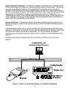
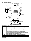
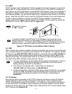
2.3 Parts of the iServer Unit
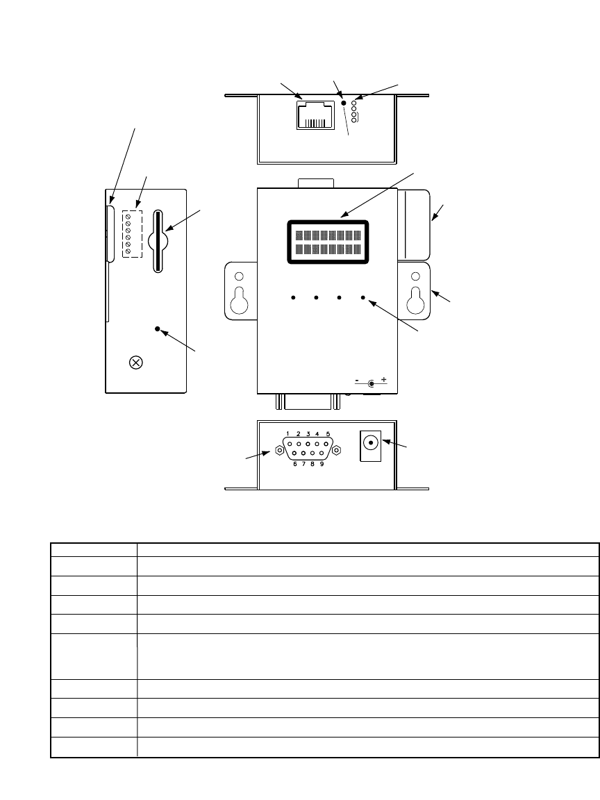
Figure 2.3 Parts of the iServer Unit
Table 2.1 Parts of iServer Unit
ETHERNET RJ45 interface for 10BASE-T connection.
iServer RESET Button: Used for power reseting the iServer board (Ethernet connection).
FLASH RESET Button: Used for power reseting the Flash Memory Card/LCD board.
ACTIVITY LED (Red) Blinking: Indicates network activities (receiving or sending packets).
NET LINK LED (Green) Solid: Indicates good network link.
DIAGNOSTICS LED (Yellow) Blinking: Indicates transmitting data from iServer to flash memory card.
When DHCP enabled, it remains solid until DHCP IP address is received.
LED (Green) Blinking: Indicates receiving data by the iServer from flash memory card
UNITS
Button: Change display units of measurement from °C to °F
TIME Button: Change display from DATE and TIME to Pressure and Temperature
STBY Button: Will stop the Flash from recording.
BKLT Button: Display Back Light
When using the small push buttons, hold the button until “WAIT” is displayed on the LCD and
then release.
9-12 Vdc
ACTIVITY
NETWORK LINK
DIAGNOSTICS
AND STATUS
iServer Reset Button
iServer LEDs
iServer
RJ45 interface
dc Power Input
Probe
Handle
Clip
BAROMETER/TEMPERATURE
UNITS STBYTIME BKLT
ETHERNET
RESET
1
8
Flash
Memory
Card
Reset
Button
Flash
Memory
Card
16 Digit
LCD Display
Buttons
DB9
Connector
Side or Bottom
Wire Entry for
Relay Connector
Removable Plug
Connector for Relays
under the Cover
6
1
Mounting
Tabs