


22
Models H71 & H84Operating Procedures
Section 6 Operating Procedures
The “Operator Parts Identification” section in this
manual has been included to identify components
referenced in these instructions. If this is the first time
you have read these procedures, please turn to the
“Operator Parts Identification” section, and familiarize
yourself with these components before proceeding
with the instructions.
Each unit stores mix in a hopper. The mix then flows
through a mix feed tube down into the freezing
cylinder. They both have 3.4 quart (3.2 liter) capacity
freezing cylinders and 20 quart (18.9 liter) mix
hoppers; one each for the Model H71 and two each for
the Model H84.
Duplicate, where they apply, the following steps for the
two freezing cylinders on the Model H84.
We begin our instructions at the point where we enter
the store in the morning and find the parts
disassembled and laid out to air dry from the p revious
night’s cleaning.
The f ollowing procedures will show you how to
assemble the parts into the freezer, sanitize them, and
prime the freezer with fresh mix in preparation to serve
your first product.
If you are disassembling the machine for the first time
or need information to get to this starting point in our
instructions, turn to page 32 “Disassembly”, and start
there.
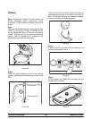
Assembly
Note: When lubricating parts, use an approved food
grade lubricant (Example: Taylor Lube HP).
MAKE SURE POWER SWITCH IS IN THE
“OFF ” POSITION! Failure to follow this instruction
may result in severe personal injury from hazardous
moving parts.
Be certain your hands are sanitized before
assembling the freezer.
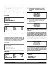
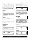
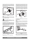
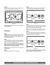
Step 1
Lubricate the groove and shaft portion that come in
contact with the bearing on the beater drive shaft. Slide
the seal over the shaft and groove until it snaps into
place. DO NOT lubricate the hex end of the drive shaft.
Fill the inside portion of the seal with 1/4” more
lubricant. Lubricate the flat side of the seal that comes
in contact with the bearing.
Figure 1
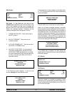
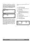
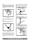
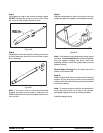
Note: Make sure the seal is not installed inside-out.
The ridge that protrudes in the center of the seal should
be on the outside.
Figure 2