


24
Models H71 & H84Operating Procedures
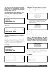
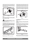
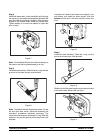
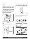
Step 4
Install the freezer door. Insert the baffle rod(s) through
the opening in the beater assembly(ies) and seat the
door flush with the freezing cylinder(s). With the door
seated on the freezer studs, install the handscrews.
T ighten equally in a criss-cross pattern to insure the
door is snug.
Figure 7
Note: On the Model H84, the short handscrews go on
the bottom and the long handscrews go on top.
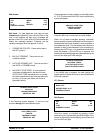
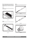
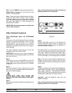
Step 5
Install the draw valve(s). Slide the three o-rings into the
grooves on the d raw valve(s) and lubricate.
Figure 8
Note: The Model H84 has three draw valves. For the
left and right draw valves, follow the assembly and
lubrication p rocedures explained previously. The
center draw valve uses a seal and an o-ring. Slide the
seal and o-ring into the grooves on the draw valve, and
lubricate.
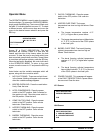
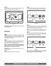
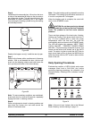
Lubricate the inside of the freezer door spout(s), top
and bottom, and insert the draw valve(s) from the
bottom until the slot in the draw valve(s) comes into
view.
Figure 9
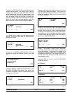
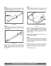
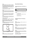
Step 6
Install the draw handle(s). Slide the o-ring into the
groove on the pivot pin, and lubricate.
Figure 10
Slide the fork of the draw handle over the bar in the slot
of the d raw valve. Secure with pivot pin.
Figure 11