


30
Models H71 & H84Operating Procedures
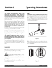
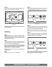
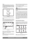
Step 6
Install the air tube assembly(ies). Lift and turn the inner
air tube of the assembled air tubes so the pin rests on
top of the outer air tube. This will close the hole in the
assembled air tubes, preventing mix in the hopper
from entering the freezing cylinder during the heating
and standby process.
Figure 29
Replace the hopper cover(s). Install the rear drip pan.
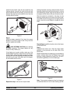
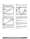
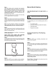
Step 7
Return to the freezer with a small amount of cleaning
solution. With a pail beneath the door, dip the end
brush into the cleaning solution and brush clean the
door spout(s) and bottom o f the draw valve(s).
Figure 30
Note: To assure sanitary conditions are maintained,
brush each item for a total of 60 seconds, repeatedly
dipping the brush in cleaning solution.
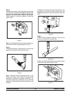
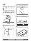
Step 8
Rinse a single service towel in cleaning solution and
wipe down the freezer door and area around the
bottom of the freezer door.
Note: Once the heating cycle has started it cannot be
interrupted. The heating cycle will take a maximum of
4 hours to complete with full hoppers.
When the heating cycle is complete, the control will
return to the STANDBY mode.
CAUTION: Do not draw product or attempt
to disassemble the unit during the Heat Treatment
Cycle. The product is hot and under extreme
pressure.
There are three phases of the heat cycle; Heating,
Holding and Cooling. Each phase has a time limit. If
any 1 of the 3 phases fails to reach the proper
temperatures within the time limit, the cycle will
automatically abort and return to the ST ANDBY mode.
The LCD will display the message “HEAT TREAT
CYCLE FAILURE -- FREEZER LOCKED--PRESS
SEL KEY”. The product may not be safe to serve. The
freezer will be locked (soft locked) out of the AUTO
mode. The option is given to press the AUTO key to
begin a new heat cycle or to press the WASH key to
place the side(s) into the OFF mode to allow a brush
clean of the unit.
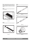
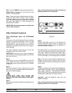
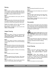
Daily Opening Procedures
Evaluate the condition of LED’s (lights) and screen
messages (Hard Lock or Soft Lock, etc.) before
performing opening procedures. As indicated in the
illustration below, 4 flashing LED’ s, indicate a “locked”
condition.
Figure 31
Note: If the unit is hard locked, refer to the “Manual
Brush Cleaning” section starting on page 31.