3. VERTICAL SCAN MODE
3-3
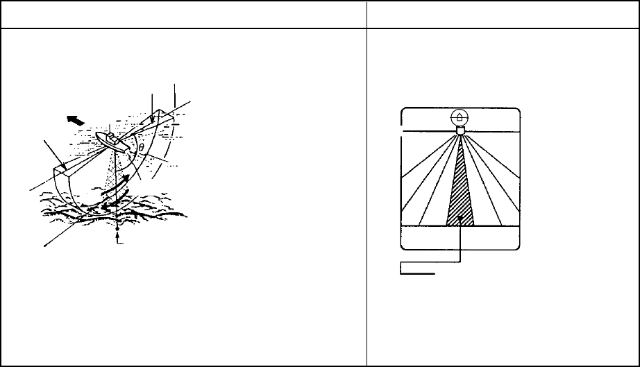
3.2.2 How the vertical scan picture is painted
The sounding beam is emitted and the information (target echoes) obtained by the
reflected echo appears in the corresponding sector as it appears on the horizontal mode.
The difference is that the training is performed only in vertical direction. It forms a
sounding area of a half-circle (like a slice of watermelon) to observe a vertical section of
underwater conditions.
Note: The tilt mechanism has a 90° range of movement. To paint the full 180° area,
therefore, the transducer is first trained through the left half (90-180°) of the area
followed by the right half (0-90°). Approximately two seconds are required to rotate
the transducer in the opposite direction before it begins training through the right or
left half.
Sounding Beam Screen Display
0°
(1) Bearing of the
sounding beam
BOW
180°
0°
Tilting direction
(2) Sector center
(3) Display area
Select the bearing of the sounding beam (1) by [TRAIN]
control, the sounding sector center (2) by the [TILT] con-
trol and the display area (3) by the [SECTOR] control.
(1) Bearing of the
sounding beam
180°
(2) Sector center,
(3) Display area
Sector center 90°.
Display range
24°.
How the vertical scan mode picture is painted


