


8
2
PANEL DESCRIPTION
2
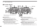
uSKIP INDICATORS (p. 36)
➥ “~” appears when the displayed memory channel is
specified as a skip channel.
➥ “
P
~” appears when the displayed frequency is speci-
fied as a program skip frequency.
iMEMORY INDICATOR (pgs. 11, 23)
Appears when memory mode
is selected.
oVSC INDICATOR (p. 17)
Appears when the VSC function is in use.
!0S-METER INDICATORS
Shows the relative signal strength while receiving signals.
(p. 14)
!1TONE INDICATORS
➥ During FM mode operation:
●
●
“”appears while the tone squelch function is in use.
(p. 41)
●
●
“”appears while the DTCS squelch function is in
use. (p. 41)
➥ During DV*
1
(Digital) mode operation:
●
●
“”appears while the digital call sign squelch func-
tion is in use. (p. 45)
●
●
“”appears while the digital code squelch function
is in use. (p. 45)
➥ During P25*
2
(Digital) mode operation:
●
●
“”appears while the digital NAC squelch function is
in use. (p. 45)
●
●
“”appears while the digital selective squelch func-
tion is in use. (p. 45)
➥ “S” appears with the “ ” or “ ” indicator while the
pocket beep function is in use. (pgs. 39, 43)
*
1
: The optional UT-118 is required.
*
2
: The optional UT-122 is required.
Some versions come with the UT-122 installed.
!2PRIORITY INDICATOR (p. 38)
Appears while priority watch is activated; blinks while pri-
ority watch is paused.
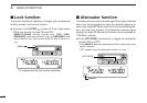
!3ATT INDICATOR (p. 15)
Appears when the ATT function is in use.
!4BUSY INDICATOR
➥ Appears when a signal is being received or the squelch
is open. (p. 14)
➥ Blinks while the monitor function is in use. (p. 14)