


10
2
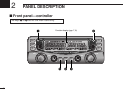
PANEL DESCRIPTION
2
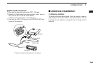
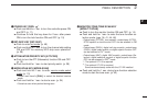
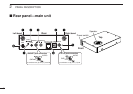
qANTENNA CONNECTORS [ANT]
Connect a 50 Ω antenna with a BNC connector and a
50 Ω coaxial cable.
[ANT1] for left band, [ANT2] for right band.
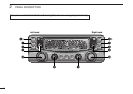
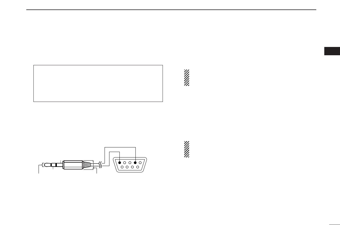
wDATA JACK [DATA]
Connect to a PC via an RS-232 cable (D-sub 9 pin) for DV
*
1
mode data communication in RS-232 format.
*
1
: The optional UT-118 is required.
ePACKET JACKS [PACKET]
Connect a TNC (Terminal Node Controller), etc. for data
communications. The receiver can support 9600 bps
packet communication (AFSK).
rUSB CONNECTOR [USB]
Connects to a PC via a supplied USB cable. This connec-
tor is only used for control software operation.
• No connection is necessary when the IC-R2500’s controller is in
use.
CAUTION: NEVER insert any other object than a USB
cable, such as a metallic object, otherwise the Main unit
may be damaged.
tEXTERNAL SPEAKER JACK [EXT SP]
Connect an 8 Ω external speaker.
• Audio output power is more than 0.5 W.
yCONTROLLER [CONTROLLER]
Connects to a controller via an extension cable. This con-
nector is only used for IC-R2500’s controller operation.
• No connection is necessary when the control software is in use.
CAUTION: NEVER insert any other object than the con-
troller cable, such as a metallic object, otherwise the
Main unit may be damaged.
uPOWER JACK [DC IN]
Accepts 12 V DC ±15% via the supplied DC power cable.
iGROUND TERMINAL [GND]
Connect this terminal to a ground.
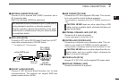
Pin 2 (RxD),
Pin 5 (GND)
to the [DATA] jack
2.5(d) mm Less than
10(d) mm
GND
RxD
1
5
69
RS-232
(DB-9 female)
Two antennas must be connected to [ANT1] and [ANT2]
during dualwatch operation or diversity operation.
Diversity operation requires two antennas of the same
performance in suitable places. Ask your antenna dealer
for installation details.