


INSTALLATION
7
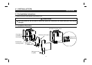
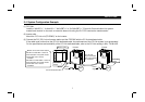
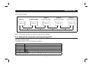
2.4 System Configuration Example
(1) PLC side
Load the "AJ61BT11", "
A1SJ61BT11
", "AJ61QBT11" or "A1SJ61QBT11" "Control & Communication Link system
master/local module" on the main or extension base unit having the PLC CPU used as the master station.
(2) Inverter side
Mount the "CC-Link unit (FR-E5NC)" on the inverter.
(3) Connect the PLC CC-Link unit master station and the FR-E5NC with the CC-Link dedicated cable.
If the cable used is other than the CC-Link dedicated cable, the performance of the CC-Link system is not guaranteed.
For the specifications and availability of the CC-Link dedicated cable, refer to the CC-Link catalog L (NA) -74108143E.
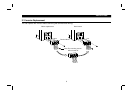
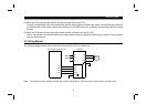
Power supply
module
CPU AJ61
BT11
CC-Link dedicated cable
Inverter
Power
supply
Motor
Motor
Inverter
Master station
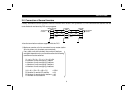
Masters for CC-Link master station
AJ61BT11/A1SJ61BT11 Control &
Communication Link system master/
local module user's manual
... IB-66721
AJ61QBT11/A1SJ61QBT11 Control &
Communication Link system master/
local module user's manual
... IB-66722
Termination
resistor
Termination
resistor
Up to 42 units
may be connected
when only inverters
are connected
Power
supply