


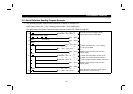
HOW TO CHECK FOR ERROR USING THE LEDS
49
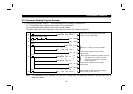
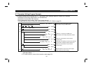
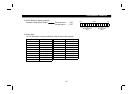
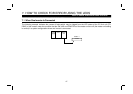
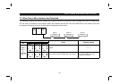
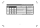
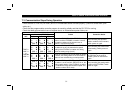
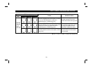
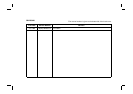
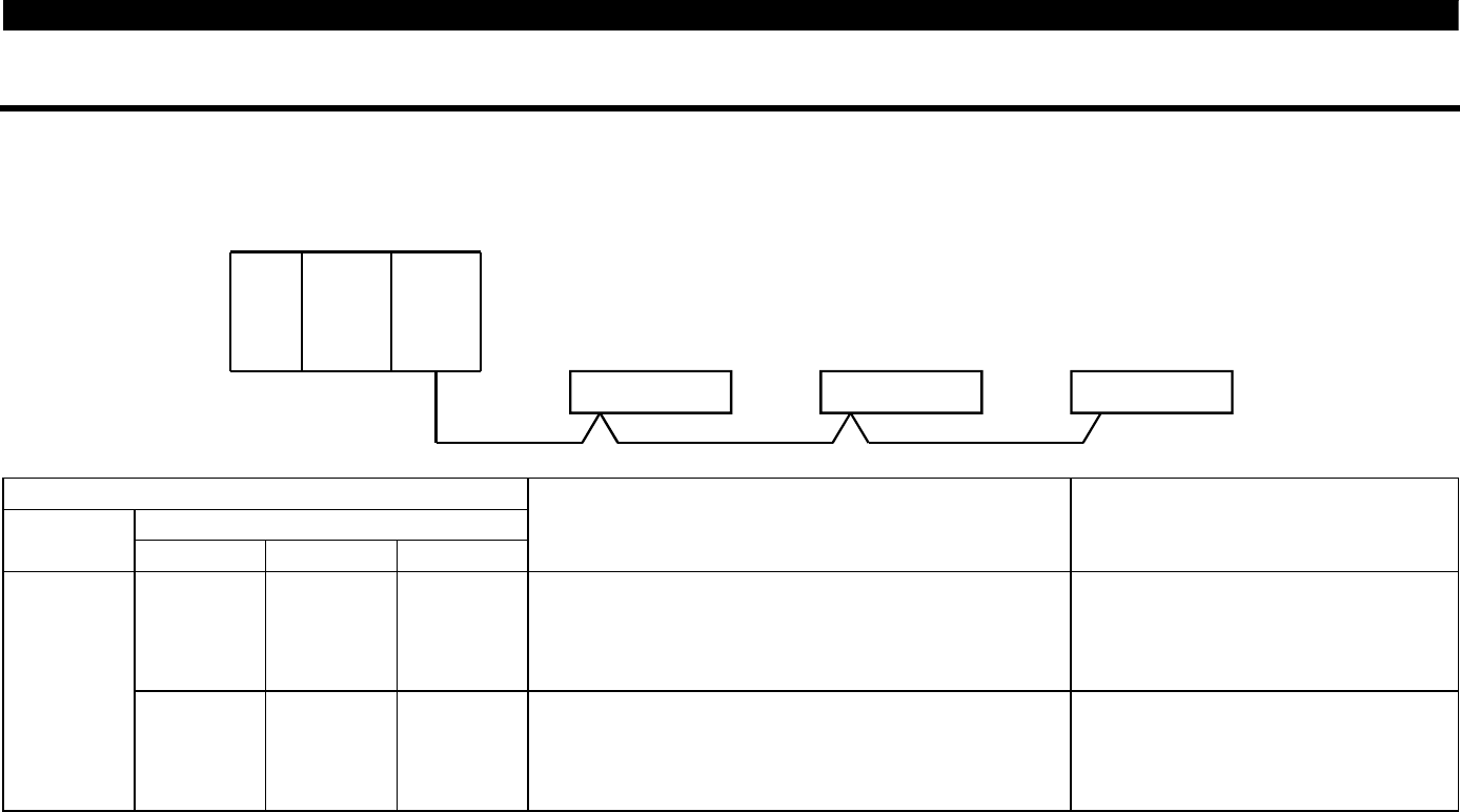
7.2 When Two or More Inverters Are Connected
The following example indicates the causes and corrective actions for faults which may be judged from the LED states of the
CC-Link units (FR-E5NCs) of the inverters under the condition that the SW, M/S and PRM LEDs of the master unit are off
(the master unit setting is proper) in the system configuration shown below:
CPU
Power
supply
Master
unit
Station 1
Inverter A
Station 2
Inverter B
Station 3
Inverter C
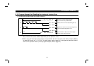
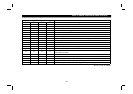
LED States
Inverters (FR-E5NC)
Master
unit
Station 1 Station 2 Station 3
Cause Corrective Action
L. RUN
"
SD
"
RD
"
L. ERR
$
L. RUN
"
SD
"
RD
"
L. ERR
$
L. RUN
"
SD
"
RD
"
L. ERR
$
Normal
TIME
$
LINE
$
or
TIME
"
LINE
$
L. RUN
$
SD
$
RD
$
L. ERR
$
L. RUN
"
SD
"
RD
"
L. ERR
$
L. RUN
"
SD
"
RD
"
L. ERR
$
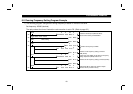
Poor contact of the FR-E5NC with the inverter
Plug the FR-E5NC securely.
Check the connector.