


FUNCTION OVERVIEW
22
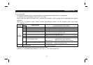
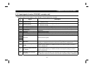
4.2.2 Operation commands
(Refer to page 35.)
Any of the following commands can be output from the PLC to the inverter as an operation command any time:
$
Forward rotation (STF)
$
Reverse rotation (STR)
$
Low speed (RL)*1
$
Middle speed (RM)*1
$
High speed (RH)*1
$
Inverter output halt (MRS)*1
The input signals marked *1 can be changed using Pr. 180 to Pr. 183 (input terminal function selection). Depending on the
setting, however, some signals do not accept the command from the PLC. For details, refer to page 17.
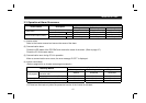
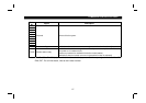
4.2.3 Running frequency
(Refer to page 40.)
The running frequency is written from the PLC to the inverter when it is changed.........Binary in 0.01Hz increments
The running frequency may either be written to E
2
PROM or to RAM. When changing the frequency continuously, always
write the data to the inverter RAM.
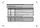
4.2.4 Parameter write
(Refer to page 39.)
Functions can be written from the PLC. Note that write during inverter operation will result in a write error.
For the parameter data code list, refer to the inverter manual.
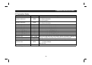
4.2.5 Parameter read
(Refer to page 38.)
Functions can be read to the PLC.
For the parameter data code list, refer to the inverter manual.