4. FUNCTION OVERVIEW
FUNCTION OVERVIEW
19
4 FUNCTION OVERVIEW
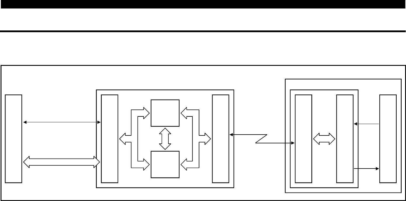
4.1 Function Block Diagram
Using function blocks, this section explains I/O data transfer to/from an inverter in CC-Link:
#
Link refresh is continuously executed between the master station and inverter in the CC-Link system at intervals of 1.1ms to
141ms (512 points).
CPU
FR-E5NC
PLC CPU
1) AJ61BT11 I/O signals
2) Buffer memory access
PLC CC-Link system master/local unit
Interface with PLC
Buffer
memory
CC-Link interface
CC-Link dedicated
cable
Inverter
CC-Link interface
I/O interface
Input
Output
Inverter CPU
1) I/O signals assigned to the CC-Link system master/local unit.
These signals are used for communication between the PLC CPU and CC-Link system master/local unit.
For further details of the signals, refer to page 23.
2) Allows input data to be read, output data to be written, and a CC-Link faulty station to be read, etc. (The FROM/TO
instruction is not needed when the automatic refresh function is used.)
Buffer memory is accessed by the FROM and TO instructions in the sequence program. For full information on the buffer
memory, refer to the CC-Link system master/local unit manual.
3) CC-Link start is dictated by the sequence program. After CC-Link is initiated, I/O refresh is continually executed
independently of (or in synchronization with) the sequence program execution.
For details, refer to the CC-Link system master/local unit manual.


