


5. COMMUNICATION SPECIFICATIONS
COMMUNICATION SPECIFICATIONS
23
5 COMMUNICATION SPECIFICATIONS
5.1 I/O Signal List
The following device No.s are those for station 1.
For stations 2 and later, the device No.s are different. (For the device No. correspondence list, refer to the master unit
manual.)
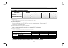
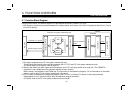
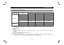
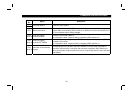
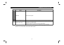
5.1.1 Output signals (master unit →
→→
→ inverter (FR-E5NC))
The output signals from the master unit are indicated. (Input signals to inverter)
Device
No.
Signal Description
RY0 Forward rotation command
OFF : Stop command
ON : Forward rotation start (Note 1)
RY1 Reserve rotation command
OFF : Stop command
ON : Reserve rotation start (Note 1)
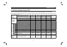
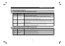
RY2
RH terminal function
(high speed)
RY3
RM terminal function
(middle speed)
RY4
RL terminal function
(low speed)
Functions assigned to RH/RM/RL are selected.
In the factory setting, multi-speed selection can be made by the combination of RH, RM
and RL. (Note 2)
RY5
RY6
RY7
RY8
Reserved (Note 5) Reserved for the system.
RY9 Output halt (MRS) When the MRS signal switches on, the inverter output stops.
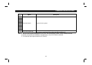
Note: 1. Switching on RY0 and RY1 at the same time gives a stop command.
2. With Pr. 180 to Pr. 183 (input terminal function selection), you can set the input signals of device No.s RY2
to RY8. For full information, refer to the inverter manual.