


©
National Instruments Corporation 2-1 NI 5911 User Manual
2
Hardware Overview
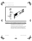
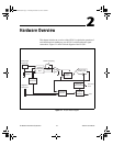
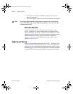
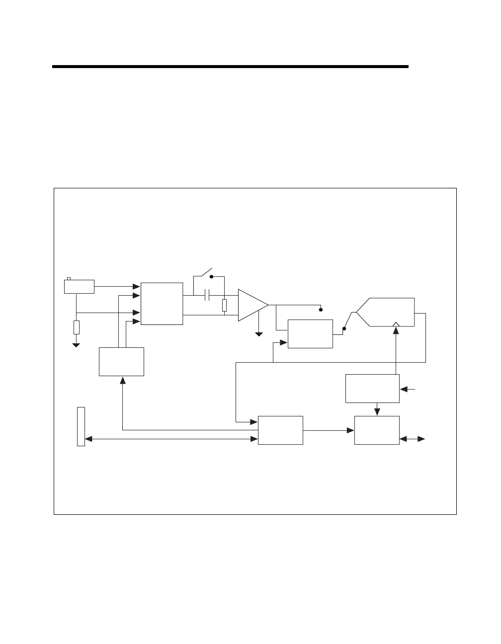
This chapter includes an overview of the NI 5911, explains the operation of
each functional unit making up your NI 5911, and describes the signal
connections. Figure 2-1 shows a block diagram of the NI 5911.
Figure 2-1.
NI 5911 Block Diagram
Protect/
Calibration
Mux
Calibration
Generator
PGA
Noise
Shaper
Reference
Clock
Data
A/D Converter
100 MHz, 8-bit
Digital Signal
Processor
Digital IO
Connector
1 kOhm
Analog Input
Connector
AC/DC Coupling
1 MOhm
Capture
Memory
Timing IO/
Memory Control
CBIHWum.book Page 1 Thursday, October 29, 1998 1:56 PM