


Appendix B Digitizer Basics
NI 5911 User Manual B-6
©
National Instruments Corporation
• Source impedance—Most digitizers and digital storage oscilloscopes
(DSOs) have a 1 MΩ input resistance in the passband. If the source
impedance is large, the signal will be attenuated at the amplifier input
and the measurement will be inaccurate. If the source impedance is
unknown but suspected to be high, change the attenuation ratio on your
probe and acquire data. In addition to the input resistance, all
digitizers, DSOs, and probes present some input capacitance in parallel
with the resistance. This capacitance can interfere with your
measurement in much the same way as the resistance does.
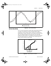
• Input frequency—If your sample rate is less than twice the highest
frequency component at the input, the frequency components above
half your sample rate will alias in the passband at lower frequencies,
indistinguishable from other frequencies in the passband. If the
signal’s highest frequency is unknown, you should start with the
digitizer’s maximum sample rate to prevent aliasing and reduce the
digitizer’s sample rate until the display shows either enough cycles of
the waveform or the information you need.
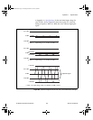
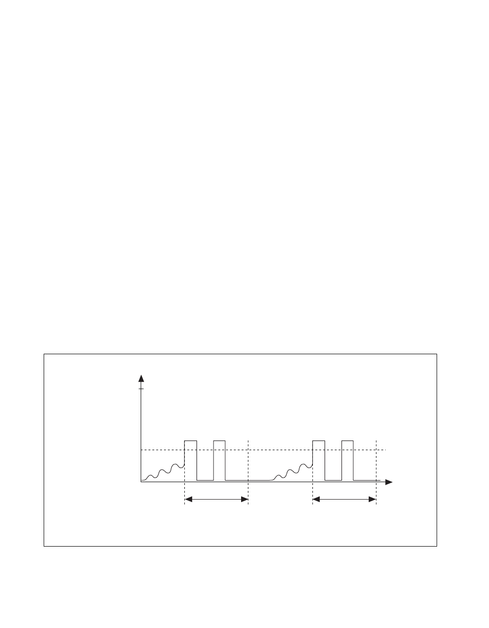
• General signal shape—Some signals are easy to capture by ordinary
triggering methods. A few iterations on the trigger level finally render
a steady display. This method works for sinusoidal, triangular, square,
and saw tooth waves. Some of the more elusive waveforms, such as
irregular pulse trains, runt pulses, and transients, may be more difficult
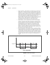
to capture. Figure B-6 shows an example of a difficult pulse-train
trigger.
Figure B-6. Difficult Pulse Train Signal
5 V
+V
t
Hold-off Hold-off
12 34
1 and 3 = Trigger Accepted
2 and 4 = Trigger Ignored
Trigger Level
CBIHWum.book Page 6 Thursday, October 29, 1998 1:56 PM