


Appendix B Digitizer Basics
NI 5911 User Manual B-2
©
National Instruments Corporation
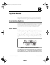
Analog Bandwidth
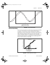
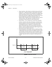
Analog bandwidth describes the frequency range (in Hertz) in which a
signal can be digitized accurately. This limitation is determined by the
inherent frequency response of the input path which causes loss of
amplitude and phase information. Analog bandwidth is the frequency at
which the measured amplitude is 3 dB below the actual amplitude of the
signal. This amplitude loss occurs at very low frequencies if the signal is
AC coupled and at very high frequencies regardless of coupling. When the
signal is DC coupled, the bandwidth of the amplifier will extend all the way
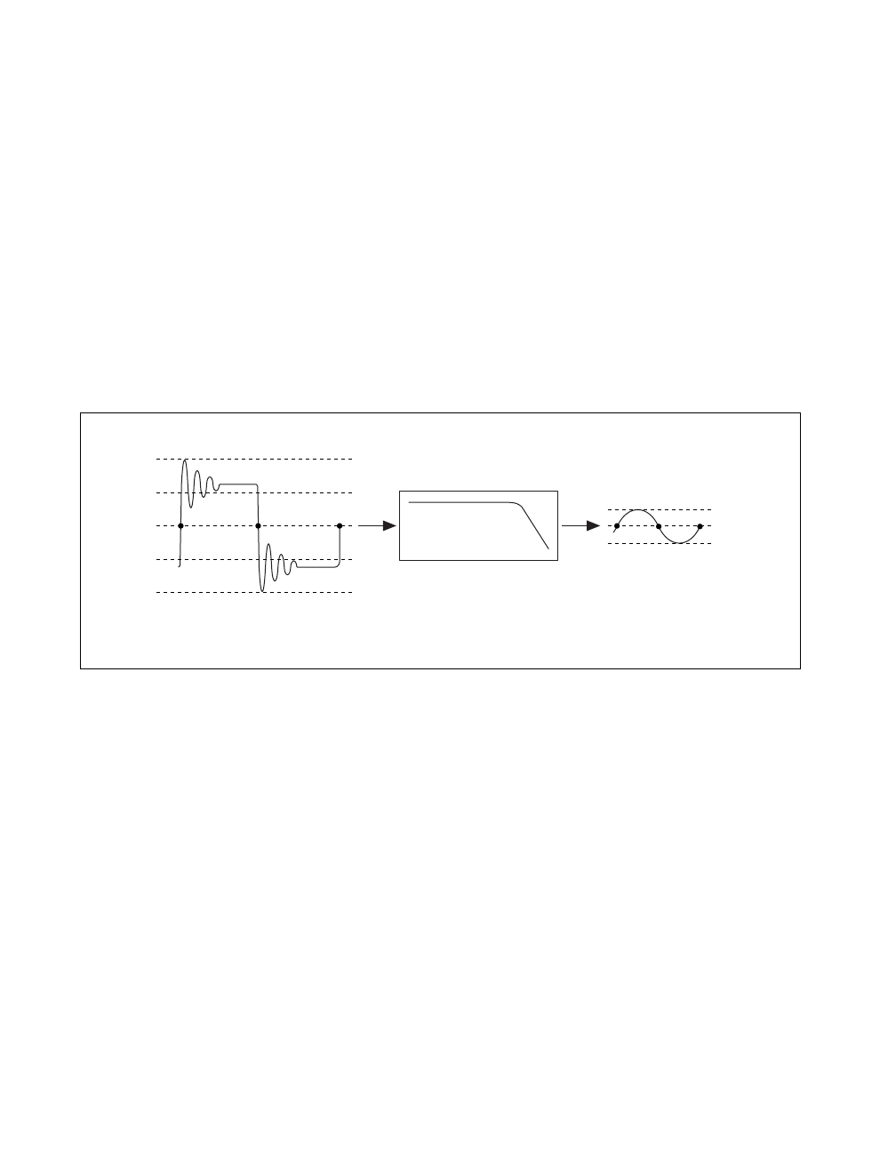
to the DC voltage. Figure B-2 illustrates the effect of analog bandwidth on
a high-frequency signal. The result is a loss of high-frequency components
and amplitude in the original signal as the signal passes through the
instrument.
Figure B-2.
Analog Bandwidth
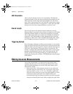
Sample Rate
Sample rate is the rate at which a signal is sampled and digitized by an
ADC. According to the Nyquist theorem, a higher sample rate produces
accurate measurement of higher frequency signals if the analog bandwidth
is wide enough to let the signal to pass through without attenuation. A
higher sample rate also captures more waveform details. Figure B-3
illustrates a 1 MHz sine wave sampled by a 2 MS/s ADC and a 20 MS/s
ADC. The faster ADC digitizes 20 points per cycle of the input signal
compared with 2 points per cycle with the slower ADC. In this example, the
higher sample rate more accurately captures the waveform shape as well as
frequency.
Bandwidth
+2 V
+1 V
0 V
0 V
+1/2 V
–1/2 V
–1 V
–2 V
Input Signal
Instrument Measured Signal
abc abc
CBIHWum.book Page 2 Thursday, October 29, 1998 1:56 PM