


Chapter 2 Hardware Overview
©
National Instruments Corporation 2-15 NI 5911 User Manual
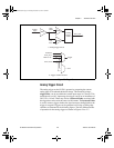
Synchronization
The NI 5911 uses a digital phase lock loop to synchronize the 100 MHz
sample clock to a 10 MHz reference. This reference frequency can be
supplied by a crystal oscillator on the board or through an external
frequency input through the RTSI bus clock line or a PFI input.
The NI 5911 may also output its 10 MHz reference on the RTSI bus clock
line or a PFI line so that other NI 5911 boards or other equipment can be
synchronized to the same reference.
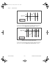
While the reference clock input is sufficient to synchronize the 100 MHz
sample clocks, it is also necessary to synchronize clock dividers on each
NI 5911 board so that internal clock divisors are also synchronized on the
different boards. These lower frequencies are important because they are
used to determine trigger times and sample position.
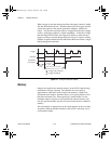
To synchronize the NI 5911 clock dividers, you must connect the boards
with a National Instruments RTSI bus cable. One of the RTSI bus triggers
must be designated as a synchronization line. This line will be an output
from the master board and an input on the slave boards. To synchronize
the boards, a single pulse is sent from the master to the slaves, which gives
them a reference time to clear the clock dividers on the boards. Hardware
arming cannot be used during a multiple board acquisition.
CBIHWum.book Page 15 Thursday, October 29, 1998 1:56 PM