


Chapter 2 Hardware Overview
©
National Instruments Corporation 2-9 NI 5911 User Manual
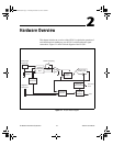
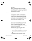
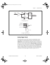
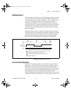
Figure 2-3. Trigger Sources
Analog Trigger Circuit
The analog trigger on the NI 5911 operates by comparing the current
analog input to an onboard threshold voltage. This threshold voltage,
triggerValue, can be set within the current input range in 170 steps. This
means that for a ±10 V input range, the trigger can be set in increments of
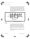
20 V/170 = 118 mV. There may also be a hysteresisValue associated with
the trigger that can be set in the same size increments. The hysteresisValue
is used to create a trigger window the signal must pass through before the
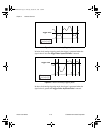
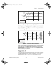
trigger is accepted. Triggers can be generated on a rising or falling edge
condition as illustrated in the following figures. The four different modes
of operation for the analog trigger are shown in Figures 2-4 to 2-7.
Gain
Analog
Input
High
Level
Low
Level
+
–
COMP
COMP
Analog
Trigger
Circuit
ATC_OUT
a. Analog Trigger Circuit
Trigger
Software
ATC_OUT
RTSI <0..6>
PFI1, PFI2
7
2
Arm
b. Trigger and Arm Sources
CBIHWum.book Page 9 Thursday, October 29, 1998 1:56 PM