


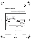
Chapter 2 Hardware Overview
©
National Instruments Corporation 2-3 NI 5911 User Manual
the cable impedances you use. As a result, most of the noise voltage occurs
at the negative input of the PGIA where it is rejected, rather than in the
positive input, where it would be amplified.
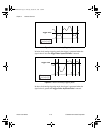
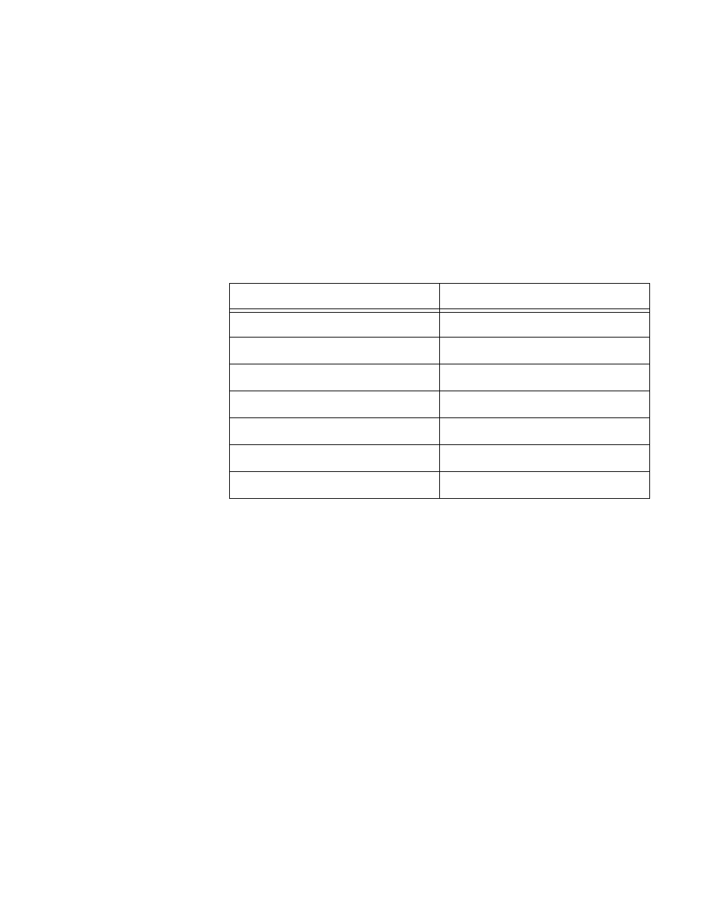
Input Ranges
To optimize the ADC resolution, you can select different gains for the
PGIA. In this way, you can scale your input signal to match the full input
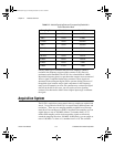
range of the converter. The NI 5911 PGIA offers seven different input
ranges, from ±0.1 V inputs to ±10 V inputs as shown in Table 2-1.
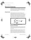
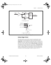
Input Impedance
The input impedance of the NI 5911 PGIA is 1 MΩ between the positive
and negative input. The output impedance of the device connected to the
NI 5911 and the input impedance of the NI 5911 form an impedance
divider, which attenuates the input signal according to the following
formula:
where V
m
is the measured voltage, V
s
is the source voltage, R
s
is the
external source, and R
in
is the input impedance.
If the device you are measuring has a very large output impedance, your
measurements will be affected by this impedance divider. For example, if
the device has 1MΩ output impedance, your measured signal will be 1/2
the actual signal value.
Table 2-1.
Input Ranges for the NI 5911
Range Input Protection Threshold
± 10 V ±10 V
± 5 V ±5 V
± 2 V ±5 V
± 1 V ±5 V
± 0.5 V ±5 V
± 0.2 V ±5 V
± 0.1 V ±5 V
V
m
V
s
R
in
R
s
R
in
+
--------------------=
CBIHWum.book Page 3 Thursday, October 29, 1998 1:56 PM