


tied to output 1. Thus the signal routed to output 1 will also be routed to the power amplifier output.
This yields a total of four physical outputs.
The EF2211 has three analog inputs labeled 1, A, and B. Input 1 is mic/line selectable, and inputs A-B
are line level only. Input 1 can also have phantom power enabled and contain channel processing,
which includes the following DSP algorithms: Acoustic Echo Cancellation, Noise Cancellation, and AGC.
An additional input, labeled T, comes from the telephone interface. The T input also has signal
processing which includes the following algorithms: Line Echo Cancellation, Noise Cancellation, and
AGC. Inputs 1, A, B, and T yield a total of 4 physical inputs.
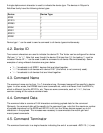
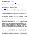
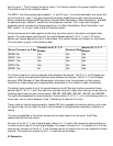
Vortex devices can be linked together so that they can share control information and digital audio
signals. The audio signals are shared on four digital busses labeled P, W, X, Y, and Z. All Vortex
devices can receive signals from all of these busses. Only certain devices can transmit on the busses.
This information is given in the following table.
Device Transmit on P Bus
Transmit on W, X, Y, Z
Busses
Receive P Bus
Receive W, X, Y, Z
Busses
EF2280 No Yes Yes Yes
EF2241 Yes Yes Yes Yes
EF2211 Yes Yes Yes Yes
EF2210 No Yes Yes Yes
EF2201 Yes No Yes Yes
The P bus is meant for routing telephone audio between the devices. The W, X, Y, and Z busses are
meant for routing microphone and auxiliary audio between the devices. The W, X, Y, and Z busses
also carry NOM (Number of Open Microphones) information from the automixer so that outputs
created from these busses can be appropriately attenuated for the number of open microphones.
The digital inputs consist of all of the signals placed on the EF Bus by the other connected Vortex
devices. Each P, W, X, Y, and Z bus can carry channels from up to eight other devices, so we have the
following digital inputs to each Vortex device: PB0-PB7, WB0-WB7, XB0-XB7, YB0-YB7, and ZB0-ZB7.
The inputs are designated by three characters: the bus letter (P, W, X, Y, or Z), a B indicating that it is
a bus input, and a number between 0 and 7 indicating the channel of the bus.
There is also an internal signal generator, labeled SG, that is capable of producing white or pink noise.
this signal is fed into the matrix so that it can be routed to the appropriate outputs for calibration or
testing.
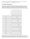
The mixing capabilities of the Vortex devices can be broken down into two parts: the EF Bus
submatrices and the main matrix.
For each of the W, X, Y, and Z signal busses, there is a 7 x 3 matrix that allows the user to define up
to three mixes of each of the four signal busses. The reason the matrix is 7 x 3 instead of 8 x 3 is that
since we can transmit on the W, X, Y, and Z busses, we do not need to mix our own channels in these
matrices. The inputs and outputs for the 7 x 3 matrices are as follows.
W Submatrix