


Simrad AP25 Autopilot
66 20221495F
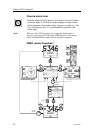
b) Compass calibration
c) Compass Offset adjustment
d) Automatic tuning
e) Viewing parameters
9. Test Autopilot Operation at Sea (refer to Sea Trial
instructions, pages
114, 132)
10. Provide the user with training (Page
133)
3.3 Unpacking and handling
Care should be taken when unpacking and handling the
equipment. A visual inspection should be made to see that the
equipment has not been damaged during shipment and that all
components and parts are present according to the packing list.
A standard AP25 autopilot system will include:
• Control unit with standard installation accessories and one
15 m (49') Robnet2 cable.
• Autopilot computer (AC10, AC20 or AC40).
• RC36 Rate Compass with 15 m (49') cable attached.
• RF300 Feedback unit with 10 m (33') cable attached and
transmission rod.
• Appropriate drive unit for the installation (unless the AP25 is
going to operate an existing drive unit or solenoids).
• Optional equipment that may have been ordered for the
installation.
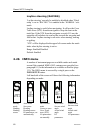
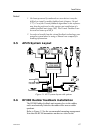
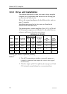
3.4 Determine system configuration
It is important to become familiar with the configuration of the
system prior to beginning the installation. The AP25 system
layout with options is shown in
Figure 3-1
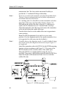
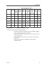
Pay particular attention to the autopilot computer/drive unit
combinations on page
72 and the chart on page 11.
As many of the units are communicating on a common network
(Robnet2), with identical connectors, the installation is
simplified. Try to mount the units within the standard cable
length supplied with each unit, if possible. Robnet2 Extension
Cable (10m) is available from your distributor.