


Installation
20221495F 79
On-Off
Vsys+
AUTOPILOT COMPUTER
MAIN PCB
ROBNET
Bus+
Vsys
Wh
Bn
Bus
Pnk Gry
Yel
AP25
CONTROL UNIT
REAR VIEW
TB15
J4
J2
J1
J3
Connect to
any of the two
Robnet2
connectors
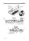
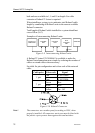
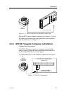
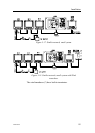
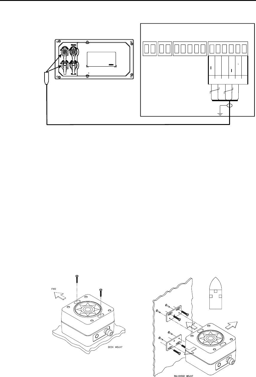
Figure 3-11 Control unit connection
J1 and J2 (top) are Robnet2 connectors. J3 and J4 are SimNet
connectors.
AP27 connection
If a Simrad AP27 is part of the system, use the JP27 Jack Point
and connect as shown on
Figure 3-9. Alternatively cut the
connector from the cable and connect the wires in parallel with
the cable shown on
Figure 3-11 using the same color code.
Note ! The AP27 cable contains an air-breathing tube. Check that the
tube is open after you have cut the cable.
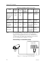
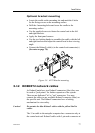
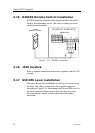
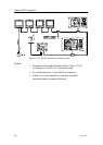
3.13 RC36 Rate Compass installation
Figure 3-12
RC36 mounting
The heading sensor is the most important part of the AP25
system and great care should be taken when deciding the