


Installation
20221495F 91
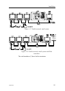
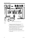
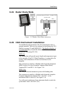
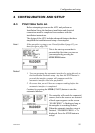
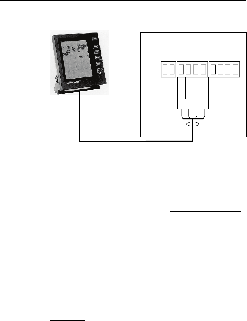
3.24 Radar Clock/Data
AC20/AC40 AUTOPILOT COMPUTER
POWER PCB
Radar
TB8
TB9
TB10
Data_h
Data_c
Clk_h
Clk_c
SIMRAD/
ANRITSU
OR
FURUNO
RADAR
Figure 3-25 Radar Clock/Data connection
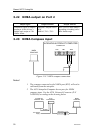
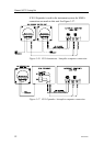
3.25 IS15 Instrument installation
For installation and operation of the IS15 instruments refer to
separate manuals. There are two options for interfacing the IS15,
SimNet (see page
83) and NMEA0183. The SimNet interface is
recommended and you need the dedicated AT15 Active Tee as
an interface item (page
88, 146).
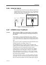
NMEA In
This connection will provide speed, depth and temperature input
to the autopilot. If an IS15 Wind Transducer is connected to the
system, wind information will also be transferred to the
autopilot.
The connection is made by a Roblink cable from the instrument
NMEA socket (4) to the Autopilot Computer Main Board,
Terminal RX1+ and RX1-. See
Figure 3-26.
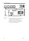
NMEA Out
This will provide the instrument system with heading data.
The connection is made by a Roblink cable from the Autopilot
Computer Main Board, terminal TX1+ and TX1– to the
instrument NMEA socket (4). See
Figure 3-26.
You will need a minimum of two instrument heads to make the
system both ‘listen’ and ‘talk’ (I/O).