


2-7
Chapter 2: Installation
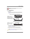
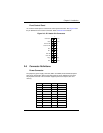
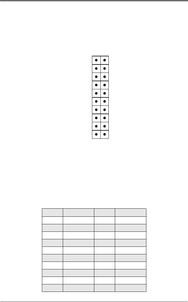
Front Control Panel
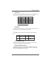
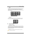
JF1 contains header pins for various front control panel connectors. See Figure 2-8 for
the pin definitions of the various connectors. Refer to Section 2-6 for details.
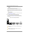
2-6 Connector Definitions
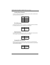
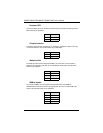
Power Connector
The proprietary power supply connector (JWR1 and JWR2) meets the SSI (Superset
ATX) 20-pin specification. Refer to the table below for the pin definitions of the ATX
20-pin power connector. This connection supplies power to the chipset, fans and
memory.
Figure 2-8. JF1 Header Pin Connectors
Pin# Definition Pin# Definition
1 GND 11 PS_ON_N
2 GND 12 5V_STBY
3GND 13GND
4 GND 14 GND
5GND 15GND
6 NC 16 NC
7 12V 17 12V
8 12V 18 12V
9 12V 19 12V
10 12V 20 12V
2019
21
Power Button
PowerLED
HDD LED
NIC 1
OH Fan Fail LED
Power Fail LED
Ground
Ground
NM 1
Vcc
Vcc
Vcc
Vcc
Vcc
Vcc
Reset
X (Key)
NIC 2
X (Key)
Ground