


2-9
Chapter 2: Installation
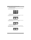
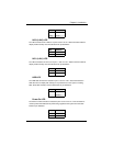
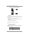
NIC2 (LAN2) LED
The LED connections for LAN2 are on pins 9 and 10 of JF1. Attach LAN LED cables to
display network activity. See the table below for pin definitions.
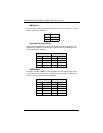
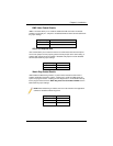
NIC1 (LAN1) LED
The LED connections for LAN1 are on pins 11 and 12 of JF1. Attach LAN LED cables to
display network activity. See the table below for pin definitions.
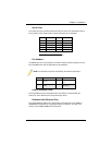
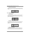
HDD LED
The HDD LED connection is located on pins 13 and 14 of JF1. Attach the hard drive
LED cable here to display disk activity (for any hard drives on the system, including
SAS, Serial ATA and IDE). See the table below for pin definitions
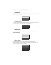
Power On LED
The Power On LED connector is located on pins 15 and 16 of JF1. This connection is
used to provide LED indication of power being supplied to the system. See the table
below for pin definitions.
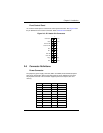
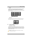
State Indication
Solid Overheat
Blinking Fan Fail
Pin# Definition
9Vcc
10 NIC2
Pin# Definition
11 Vcc
12 NIC1
Pin# Definition
13 Vcc
14 HD Active
Pin# Definition
15 5V Stby
16 Control