


1.5 Installation (19” Rack Mount Enclosure)
The Model 450 is shipped with the following standard equipment:
1. Power cord.
2. Instruction manual.
CAUTION
To avoid personal injury, always use two persons to lift and
carry the Model 450.
Upon receiving the Model 450 please do the following:
1. Verify no apparent shipping damage. (If damage has occurred please advise
shipper first, then Teledyne API.)
2. Remove all red colored shipping screws from the inside and bottom of the
instrument. There are four screws on the optical bench mounts that are
accessed from the inside of the instrument and two on the pump bracket that
are accessed from the bottom of the instrument. Note: Save these shipping
screws and re-install them whenever the unit is shipped to another
location.
3. When installing the Model 450, allow a minimum of 4 inches of clearance at
the back of the instrument and 1 inch of clearance on each side for proper
ventilation.
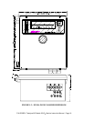
4. Connect sample inlet line(s) to the sample port on rear panel.
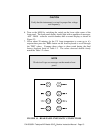
CAUTION
Connect the exhaust fitting on the rear panel (See Fig. 1.1) to a
suitable vent outside the monitor area.
5. Connect the power cord to an appropriate power outlet (see the serial number
tag for correct voltage and frequency).
NOTE
See Figure 1.1 for rear panel pneumatic connections. Sample
lines made from an inert material such as Teflon should be used
to minimize sample degradation.
P/N 02395D1 Teledyne API Model 450 O
3
Monitor Instruction Manual - Page 12