


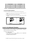

4. The M450 display will read "ADJUST ZERO:A/D=xx.x MV.” Put the probe
of a voltmeter between TP3(AGND) and TP9(DAC #0) on the top of the V/F
card.
5. The value displayed by the voltmeter should be close(+/- 20 mV) to the value
on the M450 display. If they are not close then the V/F card has probably
been configured improperly.
Adjust the Zero pot(R27) on the6. V/F card until the value on the M450 display
alue on the voltmeter to within +/- 2 mV. Note that when
e on the
7.
lay will now read "ADJUST GAIN:A/D=xx.x MV.”
2 mV.
11. The ADC is now calibrated and the M450 will automatically calibrate all the
w seconds.
ample menu.
5.5
matches the v
adjusting R27, the value on the M450 display will change, the valu
voltmeter will remain constant.
Press ENTR.
8. The M450 disp
9. Adjust the Span pot(R31) on the V/F card until the value on the M450 display
matches the value on the voltmeter to within +/-
10. Press ENTR.
DAC's. This process takes only a fe
12. Press EXIT 3 times to return to the s
Current Loop Calibration
A current loop option can be ordered that will provide 0-20mA or 4-20mA analog output
on the a an A/D - D/A
calibra
1.
2.
output with a
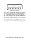
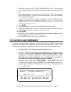
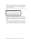
3. l, press SETUP-DIAG. Press NEXT until D/A
CALIBRATION appears and press ENTR. Press CFG and the properties for
analog output Channel 0 will be displayed on the top line. The display should
show something like:
an log output. This calibration must be repeated every time
tion is performed. To calibrate the current output, perform the following steps:
Perform an A/D - D/A calibration as outlined in Section 5.4.
Connect a Multimeter capable of measuring milliamperes to the analog output
on the rear panel. Note: When measuring the current
multimeter or similar low-impedance current measuring device, a 400-
450 ohm resistor must be placed in series with the meter to simulate a
load. Failure to do this will result in erroneous readings.
From the front pane
NEXT EXIT
DIAG D/A 0) O3_CONC_1,CURR, NOT CAL
CAL SET
P/N 02395D1 Teledyne API Model 450 O
3
Monitor Instruction Manual - Page 51