


There is one exception to this. The analog output voltage range is set by DIP Switches
on the A/D-I/O board as shown in Section 5.3.
2.1.6 RS-232 interface
The Teledyne API O
3
Monitor features an RS-232 interface which can output the
instantaneous and/or average O
3
data to another computer. It can also be used as a
command and status channel to allow a computer to control the Monitor.
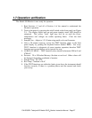
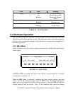
2.2 Front Panel Display
This section describes the operator interface from the point of view of the front panel.
The front panel consists of a 2-line by 40-character alphanumeric display, 8 pushbuttons,
and 3 status LED’s. Each of these features is described below.
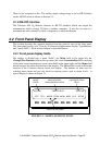
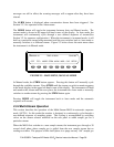
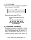
2.2.1 Front panel display fields
The display is divided into 4 main "fields": the Mode field in the upper left, the
Message/Test Function field in the top center, the ozone Concentration field consisting
of the most recent instantaneous ozone value field in the upper right, and the Menu field
which occupies the entire bottom line of the display. The Menu field is used to define the
function of the 8 buttons directly below the display. The buttons are then used for
selecting menu items and are also used for entering values such as alarm levels. A
typical display is shown in Figure 2.1.
<TST TST> MODE ALRMSTRM MSG CLR SETUP
A
UTO #1 TIME=15:58:21 O3=0.005
MODE
FIELD
MESSAGE/TEST
MEASUREMENT FIELD
CONCENTRATION
FIELD
MENU DEFINITIONS
FIGURE 2.1 - MODEL 450 FRONT PANEL
P/N 02395D1 Teledyne API Model 450 O
3
Monitor Instruction Manual - Page 32