


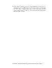
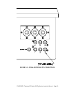
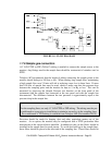
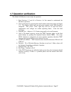

FIGURE 1.8 - FLOW DIAGRAM
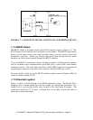
1.7.6 Sample gas connection
1/4" O.D. PTFE or FEP (Teflon) tubing is needed to connect the sample source to the
monitor. Any fittings used in the sample lines should be constructed of stainless steel or
PTFE.
Teledyne API recommends that the length of tubing connecting the sample points to the
monitor should be kept to 100 feet or less. When running long sample lines, maintaining
a high sample flow near 2 L/min will aid in reducing ozone loss in these lines. If more
than 100 feet of sample line must be used, check to make sure that the pressure drop
between the sampling point and the monitor be kept to 5 in-Hg or less. This can be
measured by observing the Sample Pressure test function on the front panel of the
instrument with the sample line connected at the rear panel and with the sample line
disconnected. The difference between the two pressures is approximately equal to the
pressure drop in the sample line.
NOTE
For the sampling lines, use only ¼” O.D. PTFE or FEP tubing. The tubing must be pre-
conditioned to ozone prior to installation to minimize ozone loss in the sampling lines.
Pre-conditioned ¼” FEP tubing is available from Teledyne API (Part number 02639)
Provision should be made for keeping dust and other particulate matter out of the
monitor. As an option, the monitor may be configured with a PTFE particulate filter
downstream of the stream selector manifold. In addition to this, in-line filters should be
installed in the sample lines for each stream. To avoid dust build up in the sample lines,
these filters should be placed at the inlet end of the sampling line. These filters should be
P/N 02395D1 Teledyne API Model 450 O
3
Monitor Instruction Manual - Page 23