


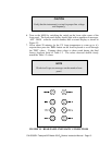
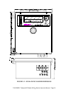
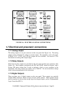
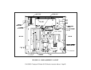
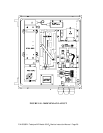
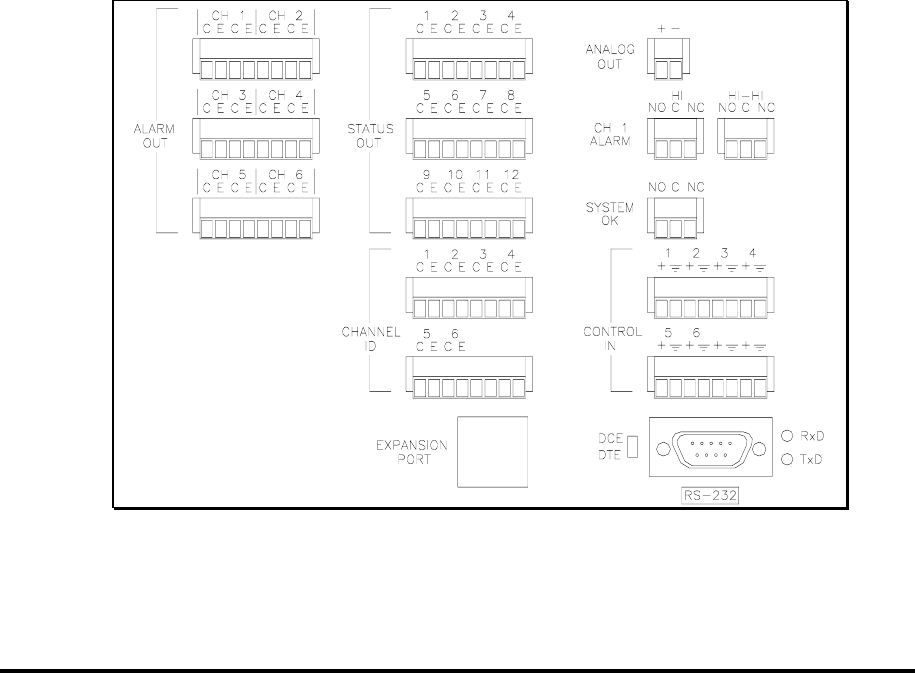
FIGURE 1.6 - ELECTRICAL SIGNAL CONNECTIONS
1.7 Electrical and pneumatic connections
1.7.1 Analog Output
The analog output is a two pin connector on the rear panel (See Figure 1.6). The analog
output can be configured for voltage or current output. The standard is a 0-5 volt output.
0-100mV, 0-1V, 0-10V, and 4-20 mA outputs are also available. See Section 5.3 for
information on setting other output ranges.
1.7.2 Relay Outputs
Three form C relay outputs are provided on the rear panel on three pin connectors (See
Figure 1.6). These outputs correspond to the ‘HI’ and ‘HI-HI’ alarms for Stream 1 and a
System OK status output that is used to indicate a fault or error condition in the
instrument. The relay contacts are rated to 3A at 240VAC. Do not exceed these ratings
when connecting equipment to the instrument.
1.7.3 Digital Outputs
There are three sets of digital outputs on the rear panel. These outputs are optically
isolated NPN transistors which can pass 50 mA of DC current. These outputs can be
used to interface to devices that accept logic-level digital inputs, such as Programmable
Logic Controllers(PLC’s).
P/N 02395D1 Teledyne API Model 450 O
3
Monitor Instruction Manual - Page 20