


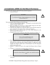
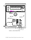
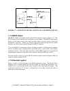
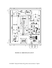

FIGURE 1.7 - CONNECTING DIGITAL OUTPUTS TO AN EXTERNAL DEVICE
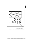
1.7.4 RS232 Output
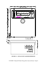
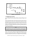
The RS232 output is provided on the 9-pin D-Sub connector shown in Figure 1.6. The
RS232 output can be connected to a computer or serial printer. The RS232 output can be
used to record alarm events with a time and date stamp or can be used to control the
instrument’s operation. Almost any function that can be done through the front panel
interface can also be done remotely through the RS232 interface.
To use the RS232 for instrument control, all that is needed is a PC(personal computer)
with an available serial communications port(COM port), a serial cable, and terminal
emulation software. The serial cable must have a female DB-9 connector on one end and
an appropriate connector on the other end to interface with the COM port on a PC.
For more details on the use of the RS232 interface, please contact Teledyne API and
request document number 01350.
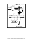
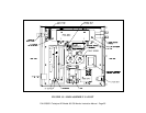
1.7.5 Pneumatic system
Figure 1.8 shows a block diagram of the M450 pneumatic system. The Model 450 is
equipped with a vacuum pump that pulls the sample gas through the instrument. The
sample flow is set using the needle valve located on the front panel flowmeter. The
sample flow should be 1-2.5 L/min. A sample flow of less than 1 L/min will result in
inaccurate ozone measurement.
P/N 02395D1 Teledyne API Model 450 O
3
Monitor Instruction Manual - Page 22