


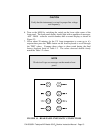
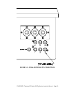
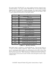
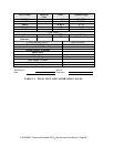
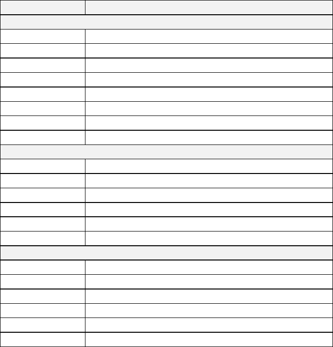
The outputs labeled ‘STATUS OUT’ are used to indicate instrument operational status
and fault conditions. The outputs labeled ‘CHANNEL ID’ are used to indicate which
channel(stream), the instrument is currently monitoring. The outputs labeled ‘ALARM
OUT’ are used to indicate the status of the HI and HI-HI alarms for each channel. Table
1.1 below summarizes the functions of all the digital outputs.
Output Description
STATUS OUT
1 Power OK
2 Diagnostics Mode(Instrument not monitoring)
3 Temperature Fault
4 Pressure Fault
5 UV Lamp Fault
6 Flow Fault
7-11 Not Used
12 System OK(no faults)
CHANNEL ID
1 Monitoring Stream #1
2 Monitoring Stream #2
3 Monitoring Stream #3
4 Monitoring Stream #4
5 Monitoring Stream #5
6 Monitoring Stream #6
ALARM OUT
CH 1 HI and HI-HI alarms for Stream #1
CH 2 HI and HI-HI alarms for Stream #2
CH 3 HI and HI-HI alarms for Stream #3
CH 4 HI and HI-HI alarms for Stream #4
CH 5 HI and HI-HI alarms for Stream #5
CH 6 HI and HI-HI alarms for Stream #6
TABLE 1.1 DIGITAL OUTPUTS
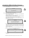
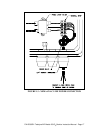
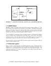
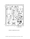
Each digital output is configured as a Collector/Emitter pair. The rear panel labels are
‘C’ and ‘E’ for these contacts, respectively. Figure 1.7 below shows the most common
way of connecting the digital outputs to an external device such as PLC. Note: Most
devices, such as PLC’s, have internal provision for limiting the current that the input will
draw from an external device. When connecting to a unit that does not have this feature,
external dropping resistors must be used to limit the current through the transistor output
to 50mA or less.
P/N 02395D1 Teledyne API Model 450 O
3
Monitor Instruction Manual - Page 21