


10
Please Do Not Return This Product To The Store. Contact your local Wayne-Dalton dealer. To find your local Wayne-Dalton dealer, refer to your local
yellow pages business listings or go to the Find a Dealer section online at www.Wayne-Dalton.com
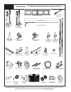
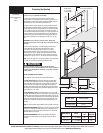
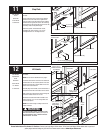
Tools Needed:
Tools Needed:
7
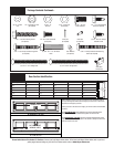
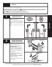
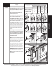
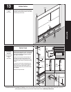
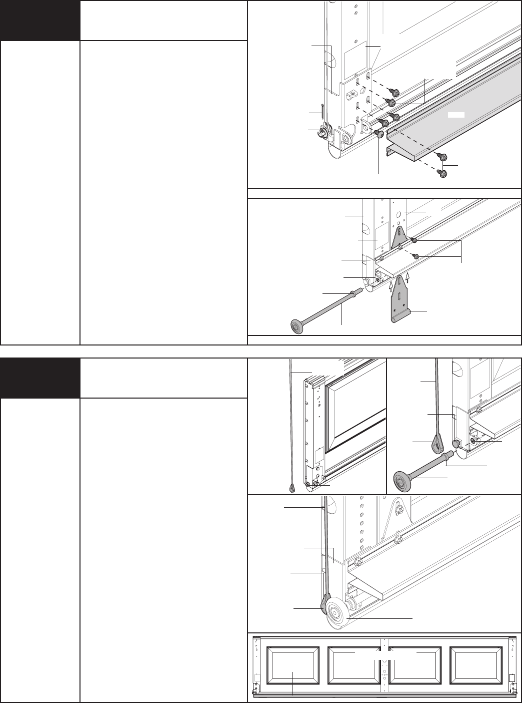
Counterbalance Cables
NOTE: For door section identification see page 4.
IMPORTANT: RIGHT AND LEFT HAND IS ALWAYS
DETERMINED FROM INSIDE THE GARAGE LOOKING
OUT.
Uncoil the counterbalance cables and place the cable
loop on the milford pin.
NOTE: Depending on the bottom bracket that was
provided with your door, you may already have the
counterbalance cable installed. Refer to Step 6.
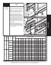
Insert a short stem roller with a spacer into bottom
bracket of the bottom section.
Repeat for other side.
NOTE: Verify astragal (bottom seal) is aligned with
door section. If there is more than 1/2” excess
astragal on either side, trim astragal even with door
section.
Bottom
section
Milford pin
Short stem
roller
Hinge
tube
Milford
pin
Bottom section
Astragal
None
Bottom
bracket
Milford pin
Counterbalance
cable
Counterbalance
cable
Cable
loop
Cable
loop
Counterbalance
cable
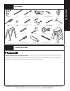
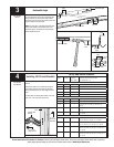
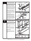
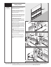
Attach the bottom bracket to the bottom corners
of section and secure using (4) 1/4”-20 x 7/8” self
drilling screws and (1) 1/4”-20 x 5/8” tamper-
resistant self drilling screw as shown. Repeat for
other side. Position a u-bar (if applicable) over the
bottom brackets and center the u-bar side to side on
the bottom section. Secure the u-bar / bottom bracket
into the endstile using (2) 1/4”-14 x 7/8” self drilling
screws. Repeat for the right hand side. Now, finish
securing the u-bar to the section using (2) 1/4”- 14 x
7/8” self drilling screws at each center stile location.
NOTE: All doors are provided with the tamper
resistant fasteners for the bottom brackets. However,
the professional installer is most likely to have the
proper tool to install this fastener. If the homeowner
does not have the proper tool to install the tamper
resistant fastener, use a regular 1/4” - 14 x 7/8” self
drilling screw in its place.
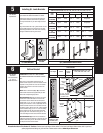
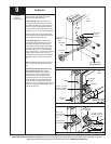
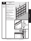
For windload specification option codes 1124,
1125, 1142 and 1144: Extension brackets, long
stem rollers and spacer are required. Position the
extension bracket flush against the end stile and
slide it underneath the u-bar (if applicable). Align
the extension bracket with the bottom bracket by
inserting a long stem roller with spacer through the
bottom bracket and extension bracket hinge tubes.
Attach the extension bracket to the endstile with (2)
1/4” -14 x 7/8” self drilling screws as shown.
Repeat for other side.
Bottom Bracket Continued...
Long stem
roller
Spacer
Long stem roller
Spacer
(A) or (B)
bottom bracket
Hinge tubes of bottom bracket
Bottom
section
Hinge tube
of extension
bracket
U-bar
Stile
(2) 1/4”- 14 x 7/8”
Self drilling screws
Warning
label
Bottom
bracket
End
Stile
(B)
Washer
(2) 1/4”- 14 x 7/8”
Self drilling screws
(1) 1/4”- 14 x 5/8”
Self drilling tamper-resistant
screw
U-bar
Cotter Pin
(4) 1/4”- 14 x 7/8”
Self drilling screws
Warning
label
WINDLOAD SPECIFICATION OPTION CODES 1124, 1125, 1142 AND 1144