


12
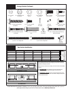
Please Do Not Return This Product To The Store. Contact your local Wayne-Dalton dealer. To find your local Wayne-Dalton dealer, refer to your local
yellow pages business listings or go to the Find a Dealer section online at www.Wayne-Dalton.com
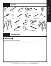
Tools Needed:
(A)
9
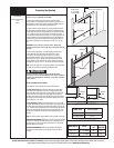
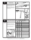
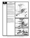
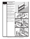
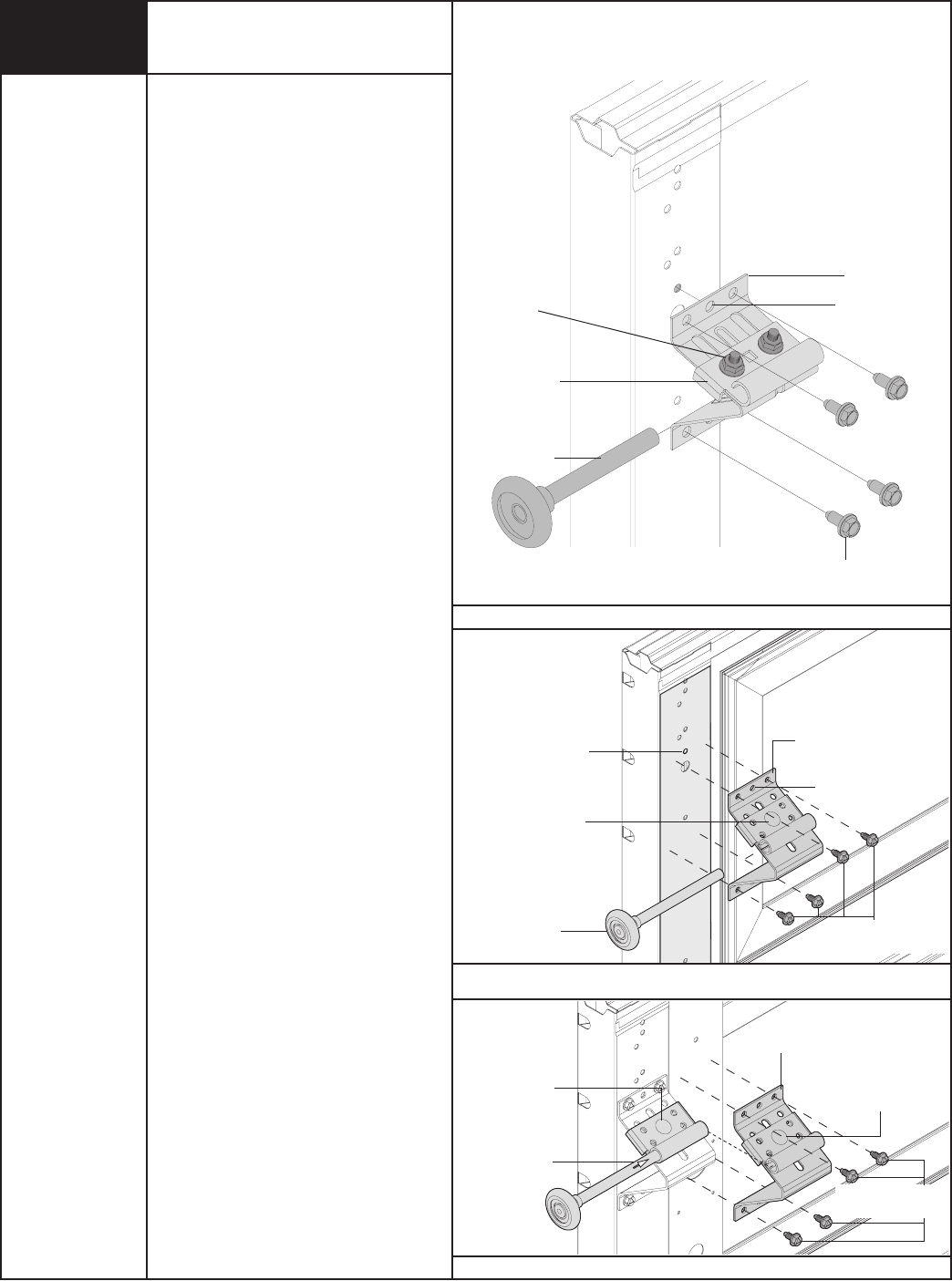
Top Bracket
Power Drill
7/16” Socket Driver
NOTE: Refer to illustrations (A) or (B) to determine
which top bracket was supplied with your door.
Follow the corresponding step below:
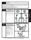
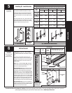
For Top Bracket (A): Align upper-center hole of
the top bracket base with #6 hole in the end stile
(See End Stile Hole Pattern on Pg 9). Ensure the top
bracket base is level and aligned with the edge of
the section. Secure the top bracket assembly to the
endstile using (4) 1/4” - 20 x 7/8” self drilling screws.
Insert a short stem roller into the top bracket slide.
The top bracket slide will be adjusted and tightened
in Step 18. Repeat for the opposite side.
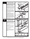
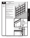
For Top Bracket (B): Align upper-center hole of
the top bracket base with #6 hole in the end stile
(See End Stile Hole Pattern on Pg 9). Ensure the
top bracket base is level and aligned with the edge
of the section. Secure the top bracket assembly to
the endstile using (4) 1/4” - 20 x 7/8” self drilling
screws. Loosen the 5/16” - 18 nut on the top bracket
assembly. Insert a short stem roller into the top
bracket slide. The top bracket slide will be adjusted
and tightened in Step 18. Repeat for the opposite
side.
NOTE: For windload specification option codes 1124,
1125, 1142 and 1144, do not insert a short shaft
roller.
For windload specification option codes 1124,
1125, 1142 and 1144 (C): Two top bracket
assemblies and a long stem roller are required.
Loosen the 5/16” - 18 nut on the top bracket
assembly and position it flush against the stile,
and centered on the stile. Insert a long stem roller
through both slides of the top bracket assembly’s
to align. Secure the top bracket assembly to stile
using (4) 1/4” - 20 x 7/8” self drilling screws. The top
bracket slide will be adjusted and tightened in Step
18. Repeat for other side.
Top bracket
assembly
End
stile
Top
section
#6 hole
Center hole
(4) 1/4”- 14 x 7/8”
Self drilling screws
Short stem
roller
(1) 5/16”- 18 x 5/8”
Carriage bolt and (1)
5/16”- 18 hex nut
Stile
Top bracket
assembly
Long stem roller
(1320/1340 only)
(1) 5/16”- 18 x
5/8” Carriage bolt
and (1) 5/16”- 18
hex nut
(4) 1/4”- 14 x 7/8”
Self drilling screws
(1) 5/16”- 18 x 5/8”
Carriage bolt and (1)
5/16”- 18 hex nut
(C)
(B)
Top bracket
base
(4) 1/4”- 20 x 7/8”
Self drilling screws
Short stem
roller
Top bracket
slide
End
stile
Center hole
Top
section
(2) 1/4”-20
Flange hex
nut
s