


9
Please Do Not Return This Product To The Store. Contact your local Wayne-Dalton dealer. To find your local Wayne-Dalton dealer, refer to your local
yellow pages business listings or go to the Find a Dealer section online at www.Wayne-Dalton.com
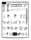
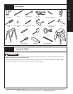
Tools Needed:
Tools Needed:
INSTALLATION
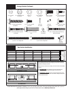
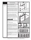
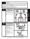
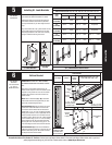
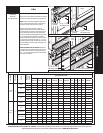
Installing Q.I. Jamb Brackets
5
Q.I. JAMB BRACKET SCHEDULE
WINDLOAD SPECIFICATION 1100, 1101, 1102, 1120, 1121, 1122, 1123, 1140, 1141, 1143
DOOR
HEIGHT
1ST SET 2ND SET 3RD SET
JAMB BKT POSITION JAMB BKT POSITION JAMB BKT POSITION
6’0”
(4 SECTIONS)
QIJB - 9 Middle QIJB - 11 Middle Not applicable
6’6”
(4 SECTIONS)
QIJB - 9 Middle QIJB - 10 Bottom Not applicable
7’0”
(4 SECTIONS)
QIJB - 9 Middle QIJB - 10 Bottom Not applicable
7’6”
(5 SECTIONS)
QIJB - 9 Top QIJB - 10 Middle QIJB - 11 Middle
8’0”
(5 SECTIONS)
QIJB - 9 Top QIJB - 10 Middle QIJB - 11 Middle
LEFT SIDE SHOWN
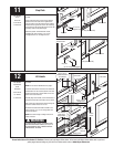
(Q.I.) JAMB BRACKET INSTALLATION
RIGHT SIDE SHOWN
Twist lock
tabs
Top hole
Bottom hole
Middle hole
QUICK INSTALL
FEATURE
Q.I. JAMB BRACKET
Q.I. jamb bracket
NOTE: The following (Q.I.) denotes a quick install
jamb bracket. No additional hardware is needed.
Measure the length or the vertical track. Using the
jamb bracket schedule, determine the placement
of the jamb brackets for your door height and track
type.
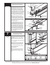
Align the twistlock tab on (Q.I.) jamb bracket with the
quick install feature in the track and turn the jamb
bracket perpendicular to the track so the mounting
flange is toward the back leg of the track.
Tape Measure
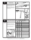
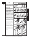
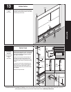
NOTE: For door section identification see page 4.
IMPORTANT: RIGHT AND LEFT HAND IS ALWAYS
DETERMINED FROM INSIDE THE GARAGE LOOKING
OUT.
Refer to the u-bar schedule to determine if the
bottom section requires a u-bar. If the bottom section
requires a u-bar, position the u-bar over the bottom
brackets and center the u-bar side to side on the
bottom section.
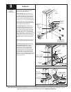
NOTE: Refer to illustrations (A) or (B) to determine
which bottom bracket was supplied with your door.
Follow the corresponding step below:
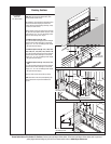
BOTTOM BRACKET (A): Align the center hole of left
hand bottom bracket with hole #3 in the end stile
of the bottom section. Attach the left hand bottom
bracket with (1) 1/4”-14 x 5/8” self tamper-resistant
drilling screw. Position a u-bar (if applicable) over the
bottom brackets and center the u-bar side to side on
the bottom section. Secure the u-bar / bottom bracket
into the endstile using (2) 1/4”-14 x 7/8” self drilling
screws. Repeat for the right hand side. Now, finish
securing the u-bar to the section using (2) 1/4”-14 x
7/8” self drilling screws at each center stile location.
BOTTOM BRACKET (B): Uncoil the counterbalance
cables and secure the cable loop to the clevis pin and
bottom bracket using a 5/16” flat washer and cotter
pin. Repeat for other bottom bracket.
6
Bottom Bracket
Power Drill
7/16” Socket Driver
1/4” Torx bit
Needle Nose Pliers
1
2
3
4
5
6
7
7
6
5
4
3
2
1
END STILE HOLE
PATTERN (LEFT SIDE
IS SHOWN. RIGHT
SIDE IS OPPOSITE.)
U-Bar Schedule
Door Height Section
Position of
u-bar on
section
Windload Option Codes: 1104 / 1123 /
1124 / 1125 /1142 / 1143 / 1144
6’- 0” to 8’- 0” Bottom Bottom X
Clevis
Pin
Counterbalance
cable
(A)
Warning
label
Bottom
bracket
(1) 1/4”- 14 x 5/8”
Self drilling tamper-
resistant screw
Bottom
section
End stile
U-bar
#3 Hole
(2) 1/4”- 14 x 7/8”
Self drilling screws
(B)
Left hand
bottom
bracket